
Corneal-ablation-amount determining apparatus and a corneal surgery apparatus

a technology of determining apparatus and amount, which is applied in the field of corneal surgery apparatus, can solve the problems of glare or halo in night vision, long surgical time, and prone to inputting errors, and achieve the effect of simple methods and reduced parts

Inactive Publication Date: 2006-02-07
NIDEK CO LTD
View PDF22 Cites 3 Cited by
  • Summary
  • Abstract
  • Description
  • Claims
  • Application Information

AI Technical Summary

Benefits of technology

[0008]An object of the invention is to overcome the problems described above and to provide a corneal surgery apparatus capable of reducing parts where a corneal curvature suddenly varies in an ablation area and an apparatus for determining a corneal ablation amount, with simple methods.

Problems solved by technology

If there are a number of parts where the corneal curvature suddenly varies, there is a problem that they cause a glare or a halo in night vision.
In addition, since it is necessary to manually input the correction amount and the ablation size (diameter) for each of the stages, there are such problems of that the inputting is laborsome, an error in inputting is apt to occur, the number of the divided stages is limited because of the manual inputting, an appropriateness of inputting depends on experiences of an operator, and the like.
Furthermore, there is a problem of that, in the case of a surgery divided into a plurality of the stages, surgical time becomes longer.

Method used


Image

  • Corneal-ablation-amount determining apparatus and a corneal surgery apparatus
  • Corneal-ablation-amount determining apparatus and a corneal surgery apparatus
  • Corneal-ablation-amount determining apparatus and a corneal surgery apparatus

Examples


Embodiment Construction

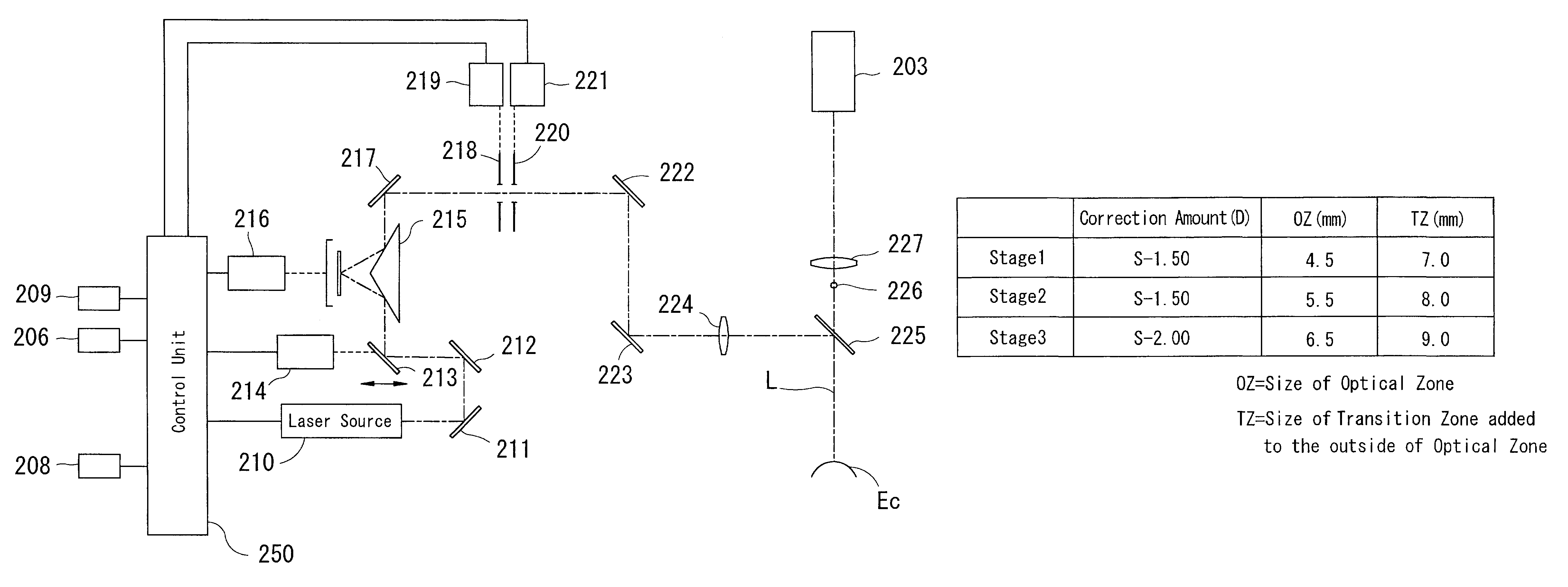
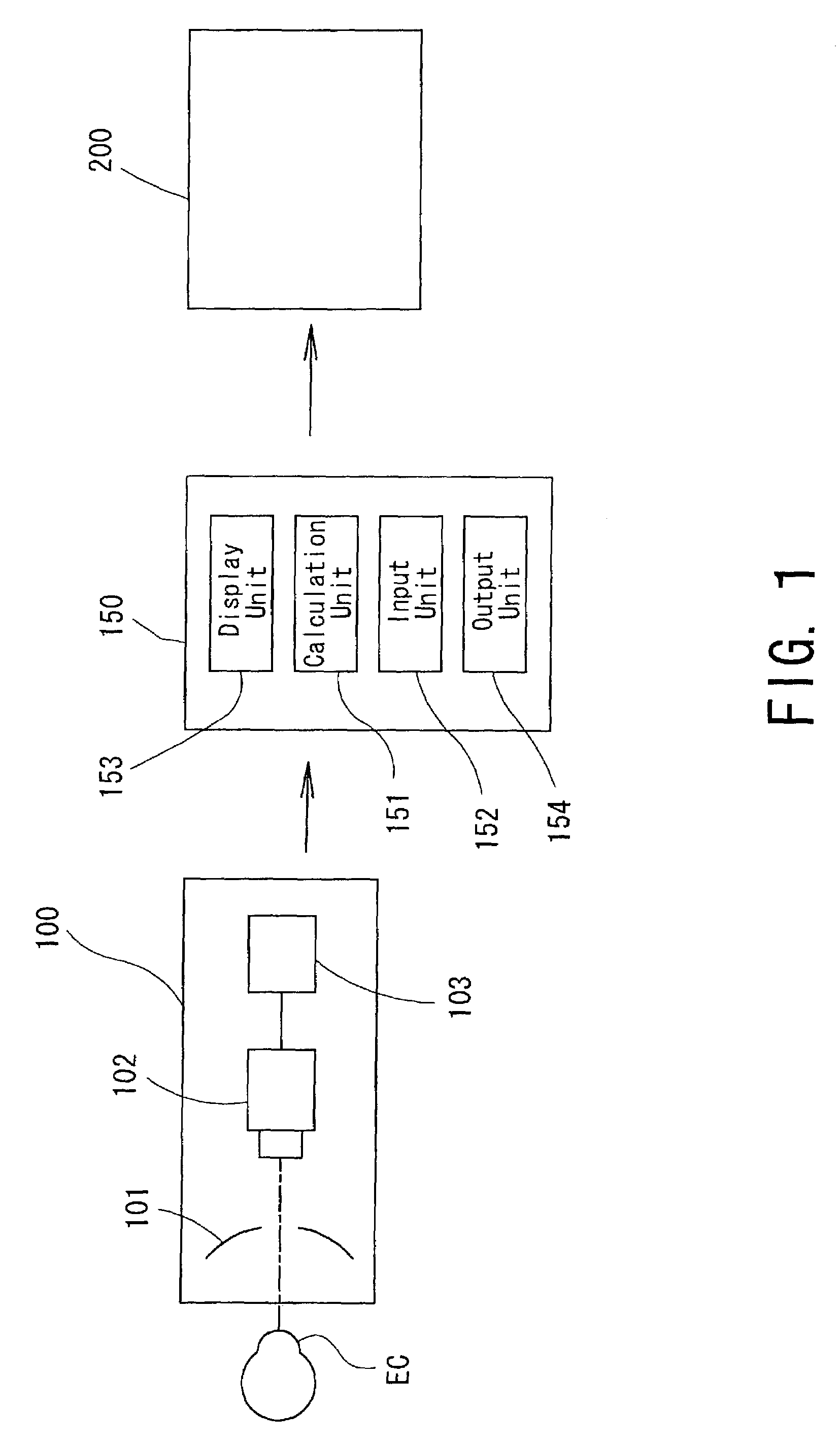
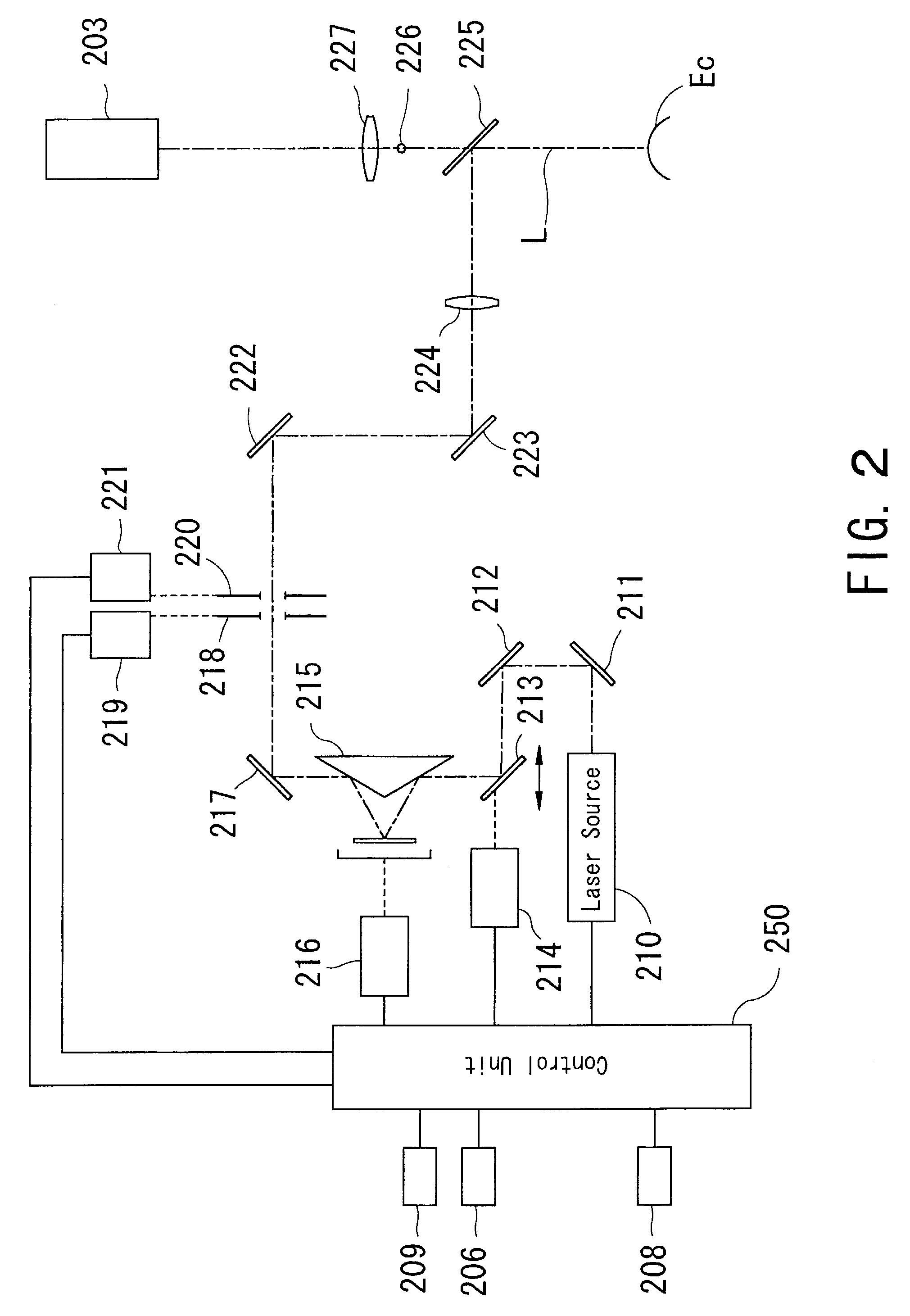
[0022]A detailed description of one preferred embodiment of a corneal-ablation-amount determining apparatus and a corneal surgery apparatus embodied by the present invention is provided below with reference to the accompanying drawings. FIG. 1 is a block diagram showing a schematic configuration of a corneal surgery apparatus system consistent with the present invention.

[0023]A corneal-shape measurement apparatus 100 obtains data on the corneal shape of a patient's eye (eye to be operated on) being a factor for determining a corneal ablation amount. The measurement apparatus 100 is provided with projecting means 101 for projecting a number of annular placido rings onto a cornea EC of the patient's eye, image pickup means 102 for picking up images of the rings, and detecting means 103 for processing the picked up images to detect edges of the ring images and obtaining a corneal curvature distribution over a wide range.

[0024]A calculation apparatus 150 calculates the corneal ablation ...


PUM


Abstract

A corneal surgery apparatus capable of reducing parts where a corneal curvature suddenly varies, and an apparatus for determining a corneal ablation amount. The corneal-ablation-amount determining apparatus includes a data input unit which inputs data on a correction amount of a patient's eye and data on a size of a second ablation zone for connecting a first ablation zone for securing the correction amount with a non-ablation area, a calculation unit which divides the inputted correction amount into at least ten, obtains an ablation amount for each divided correction amount as a lens component is ablated according to a size gradually enlarged from the first ablation zone to an outer diameter of the second ablation zone for each divided correction amount, and determines a total ablation amount by summing each obtained ablation amount, and an output unit which outputs data on the determined ablation amount.

Description

BACKGROUND OF THE INVENTION[0001]1. Field of the Invention[0002]The present invention relates to a corneal surgery apparatus for ablating a cornea by irradiating a laser beam and an apparatus for determining a corneal ablation amount.[0003]2. Description of Related Art[0004]There is known a corneal surgery apparatus which ablates a cornea by irradiating a laser beam and changes a shape of the cornea in order to correct a refractive error of an eye. The apparatus of this kind ablates part of the cornea so as to remove a lens component corresponding to a correction amount from the cornea. At this time, when only an optical region (hereinafter referred to as an “optical zone”) which secures the correction amount is ablated, a boundary between an ablation area and a non-ablation area appears as a height difference. Therefore, in order to smoothly connect (join) the optical zone and the non-ablation area, the applicant has proposed, in Japanese Patent Application Unexamined Publication N...

Claims


Application Information

Patent Timeline
Patent Type & Authority Patents(United States)
IPC IPC(8): A61B18/18A61F9/007A61F9/01
CPCA61F9/008A61F9/00804A61F2009/00882A61F2009/00872A61F9/00817
Inventor OKAMOTO, KEIKIHIRAMATSU, HIROYUKI
Owner NIDEK CO LTD
Learn More