Electric machine

a technology of electric motors and windings, applied in the direction of magnetic circuit rotating parts, magnetic circuit shapes/forms/construction, windings, etc., can solve the problems of low thermal expansion coefficient and excessive bandage thickness, and achieve the effect of reducing costs

Inactive Publication Date: 2006-02-07
L 3 COMM CORP
View PDF38 Cites 22 Cited by
  • Summary
  • Abstract
  • Description
  • Claims
  • Application Information

AI Technical Summary

Benefits of technology

[0021]The rotor preferably is an external rotor. For this application, the present invention is particularly suitable since a bandage as thin as possible has to withstand high radial forces. The rotor preferably carries permanent magnets. The utilization of the bandage in connection with permanent magnets provides for a substantial decrease in costs and facilitation of mounting the permanent magnets to the rotor.

Problems solved by technology

The reason therefor is that it has turned out that the low coefficient of thermal expansion of carbon fiber material is disadvantageous for the bandage thickness, i.e. especially in case of machines subject to high thermal loads, the low coefficient of thermal expansion of the carbon fiber material leads to an excessive bandage thickness as, in addition to the normal forces to be taken up by the bandage, the forces of thermal mismatching between bandage material and the material of the individual parts of rotor and / or stator have to be taken up as well.

Method used


Image

  • Electric machine
  • Electric machine
  • Electric machine

Examples


Embodiment Construction

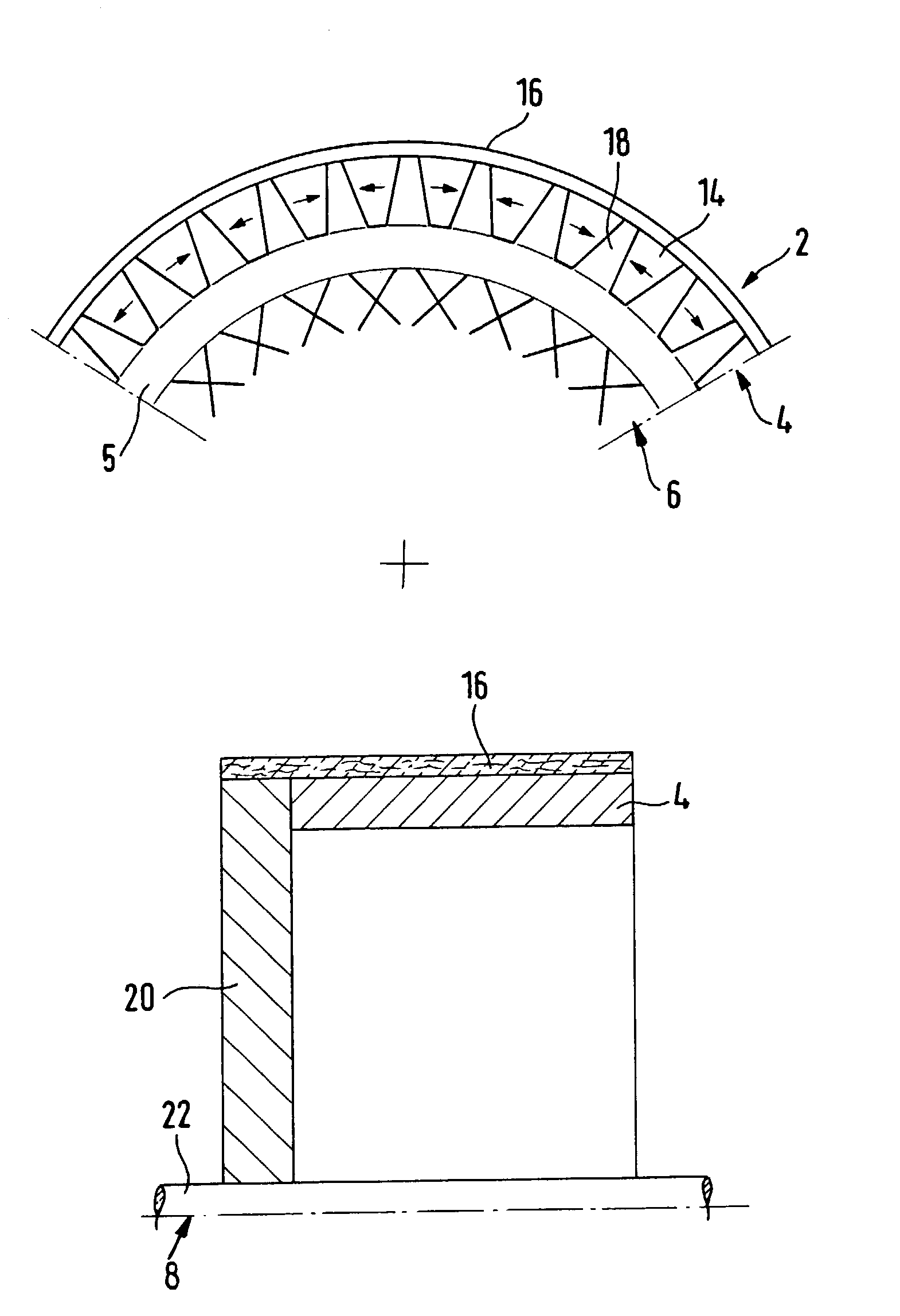
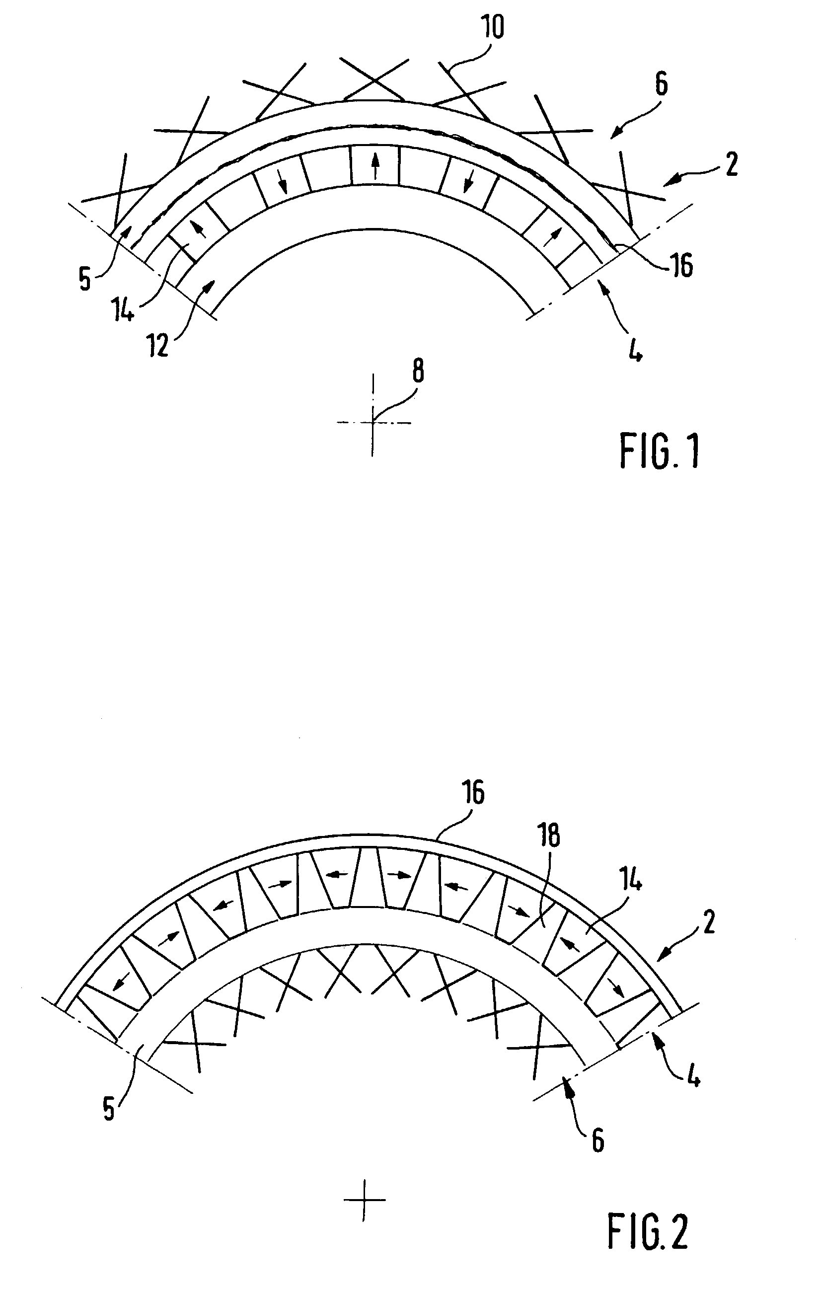
[0028]FIG. 1 illustrates the partial view of an electric machine 2, comprising a rotor 4 and a stator 6. Rotor 4 and stator 6 are arranged coaxially around a common axis 8. An air gap 5 is provided between rotor 4 and stator 6. The stator 6 carries electric winding coils illustrated schematically by crosses 10. The winding coils are arranged around winding cores (not illustrated in FIG. 1).

[0029]The rotor 4 consists of a plurality of individual parts. These include active parts, such as the magnetic yoke 12 and the permanent magnets 14. The magnetic yoke 12, which is of hollow cylindrical configuration in FIG. 1, may serve at the same time as a structural part, i.e. as supporting part for the magnets 14. As an alternative or in addition thereto, there may also be provided additional structural parts. The permanent magnets, which are magnetized in radial direction in FIG. 1 (the direction of magnetization is indicated by the arrows at permanent magnets 14), are subject to high centri...


PUM


Abstract

An electric machine (2) comprising a rotor (4) and a stator (6) arranged coaxially therewith, at least one of said rotor (4) and stator (6) being formed of a plurality of parts and there being provided a bandage (16) holding together the plurality of parts of said rotor and/or stator (6), wherein the bandage (16) is formed of an electrically non-conducting fiber material having a coefficient of thermal expansion similar to the coefficient of thermal expansion of the parts of said rotor (4) and/or stator (6).

Description

BACKGROUND OF THE INVENTION[0001]The present invention relates to an electric machine comprising a rotor and a stator arranged coaxially therewith, at least one of said rotor and stator being formed of a plurality of parts and there being provided a bandage holding together the plurality of parts of said rotor and / or stator.[0002]The present invention in general relates to the simplification of the construction and manufacture of electric machine, in particular electric motors and generators having internal or external rotors composed of individual parts as well as stators composed of individual parts, respectively. These individual parts, in conventional manufacture, are joined together using mechanically positive or form-fit connections, for example screws or mutually engaging parts etc. This kind of connection is complex in terms of working and assembly. Furthermore, there is the fact that some materials, in particular materials used for the permanent magnets, are relatively diff...

Claims


Application Information

Patent Timeline
Patent Type & Authority Patents(United States)
IPC IPC(8): H02K21/12H02K15/16H02K1/14H02K1/27
CPCH02K1/148H02K1/2786H02K1/278H02K1/279
Inventor EHRHART, PETERMUELLER, ANTON
Owner L 3 COMM CORP
Why Eureka
Try Eureka