
Device and a method for estimating the speed of a slip ring asynchronous machine

a technology of slip ring and asynchronous machines, which is applied in the direction of motor/generator/converter stopper, dynamo-electric converter control, dynamo-electric gear control, etc., can solve the problems of very fluctuating voltage signal, resistor faults, and machine faults, etc., and achieve the effect of detecting faults in the asynchronous machin

Inactive Publication Date: 2006-02-07
ABB (SCHWEIZ) AG
View PDF22 Cites 15 Cited by
  • Summary
  • Abstract
  • Description
  • Claims
  • Application Information

AI Technical Summary

Benefits of technology

[0004]The object of the present invention is to provide a device and a method for estimating the speed of a slip ring asynchronous machine, which enable an estimation of the rotor speed with a high precision and at the same time provides a product which is light, and easy to use in a control system.
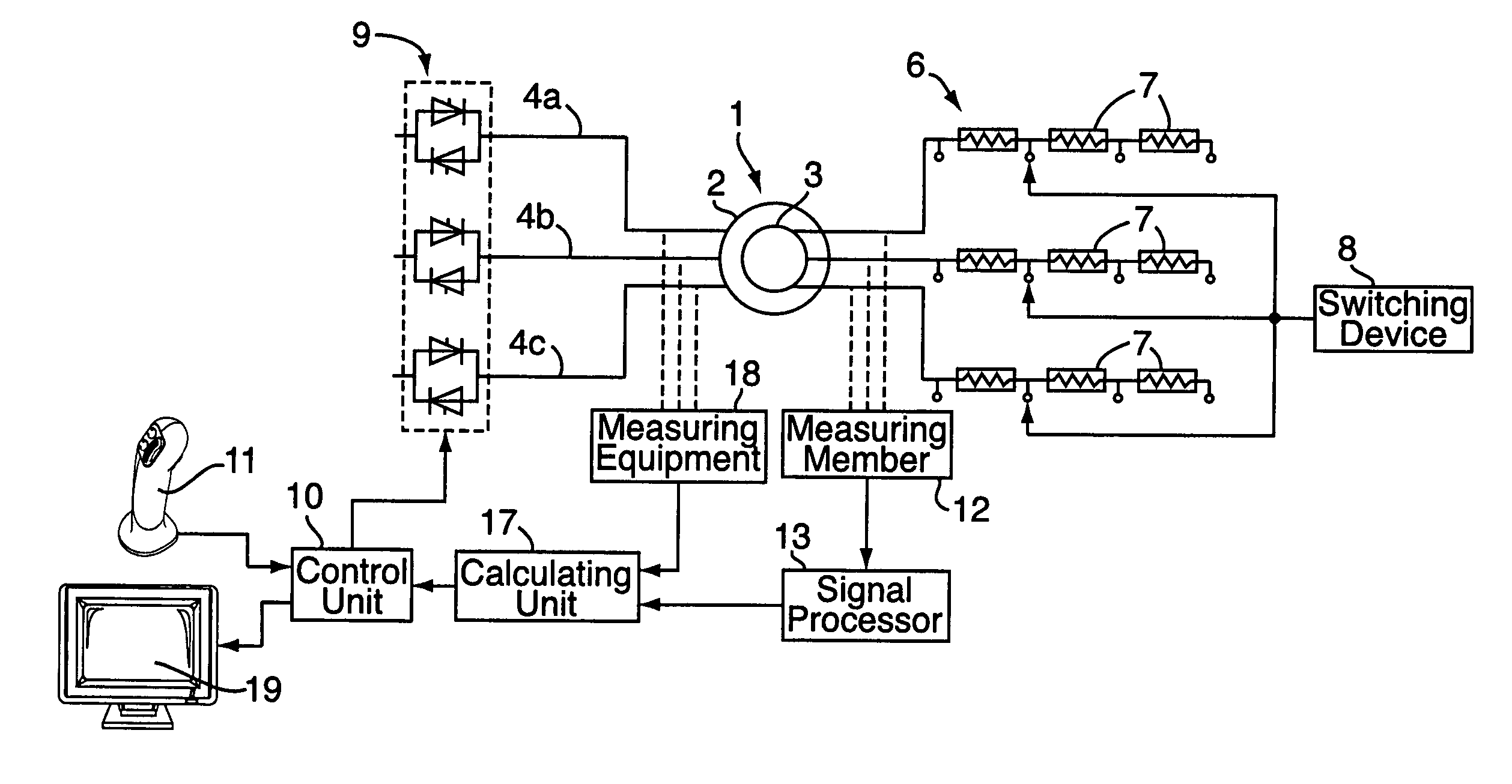
[0005]This object is achieved according to the initially mentioned device, which is characterised in that the device comprises a measuring member arranged to measure the value of the voltage in the rotor winding during at least one time period and a calculating unit which is arranged, by means of the above measured voltage, to calculate a value of the speed of the rotor. By measuring the voltage during a time period, it is possible to obtain a value of the voltage during the time period. From such values, it is possible to analyse the oscillation of the voltage during the time period and, by means of the calculating unit, to calculate the voltage frequency. By the knowledge of the calculated voltage frequency, it is easy to calculate the slip and thereafter the rotor speed by means of the calculating unit.
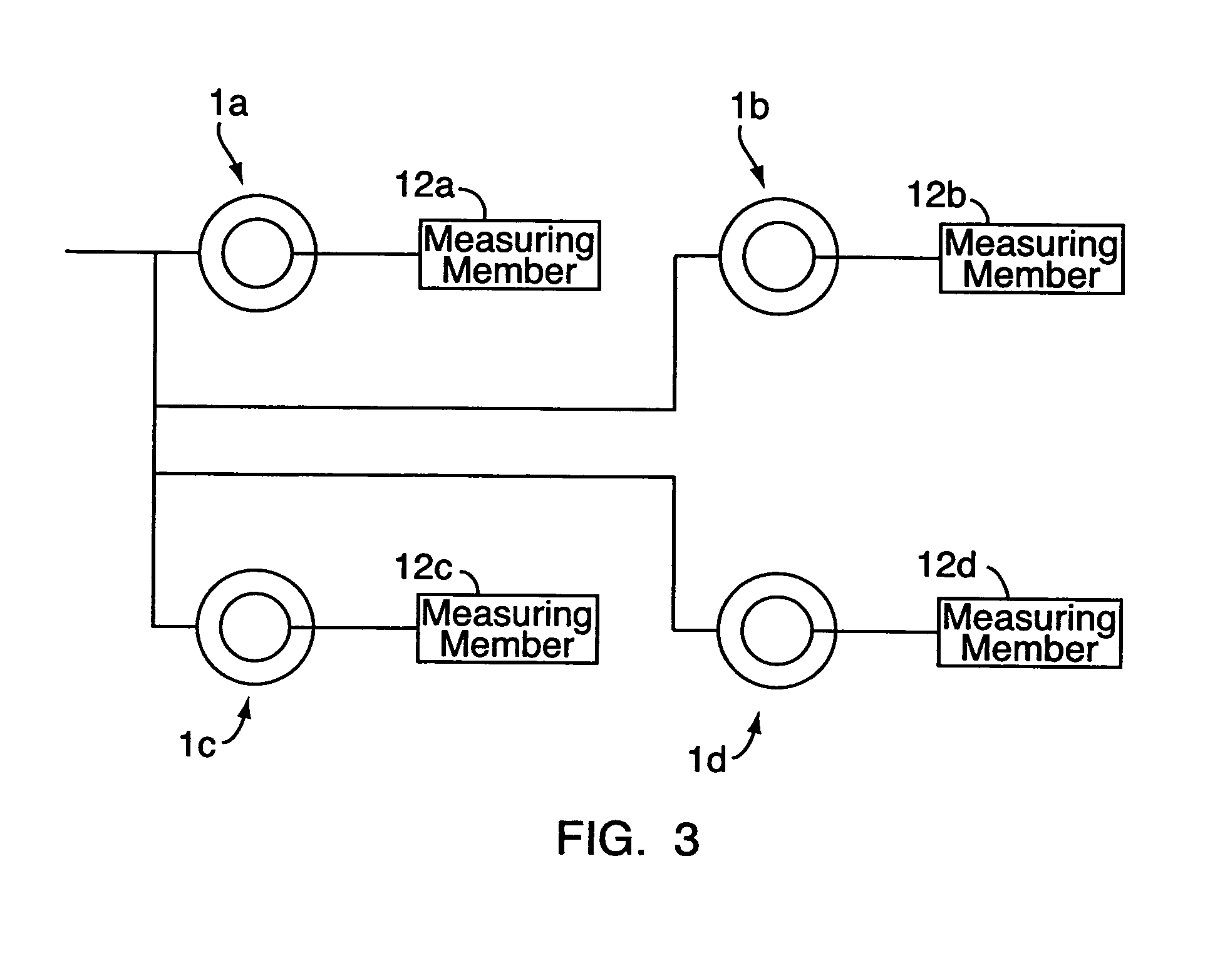
[0007]According to another preferred embodiment of the invention, the device comprises means for monitoring the calculated value of the rotor speed in order to detect faults in the asynchronous machine. Such faults may occur within the machine or the resistors, which is connected in a circuit to the rotor winding. Also breaks of electrical cables in the vicinity of the machine may be detected. Preferably, said means is arranged to monitor a number of asynchronous machines. In that way, it is possible to detect a fault in one asynchronous machine of four, for example, in a crane. By that, it is possible to prevent that the working asynchronous machines work at a too high torque, which may shorten their operating life. In order to give information to an operator, a display may be arranged to display comprehensive information about the statement of the machine.
[0013]According to another preferred embodiment of the invention, the method comprises the step to monitor the calculated value of the rotor speed in order to detect errors in the function of the asynchronous machine. Thereby, an effective detecting of faults in the asynchronous machine is obtained.

Problems solved by technology

In the most cases, the voltage signal is very fluctuating due to disturbances.
Such faults may occur within the machine or the resistors, which is connected in a circuit to the rotor winding.

Method used


Image

  • Device and a method for estimating the speed of a slip ring asynchronous machine
  • Device and a method for estimating the speed of a slip ring asynchronous machine
  • Device and a method for estimating the speed of a slip ring asynchronous machine

Examples


Embodiment Construction

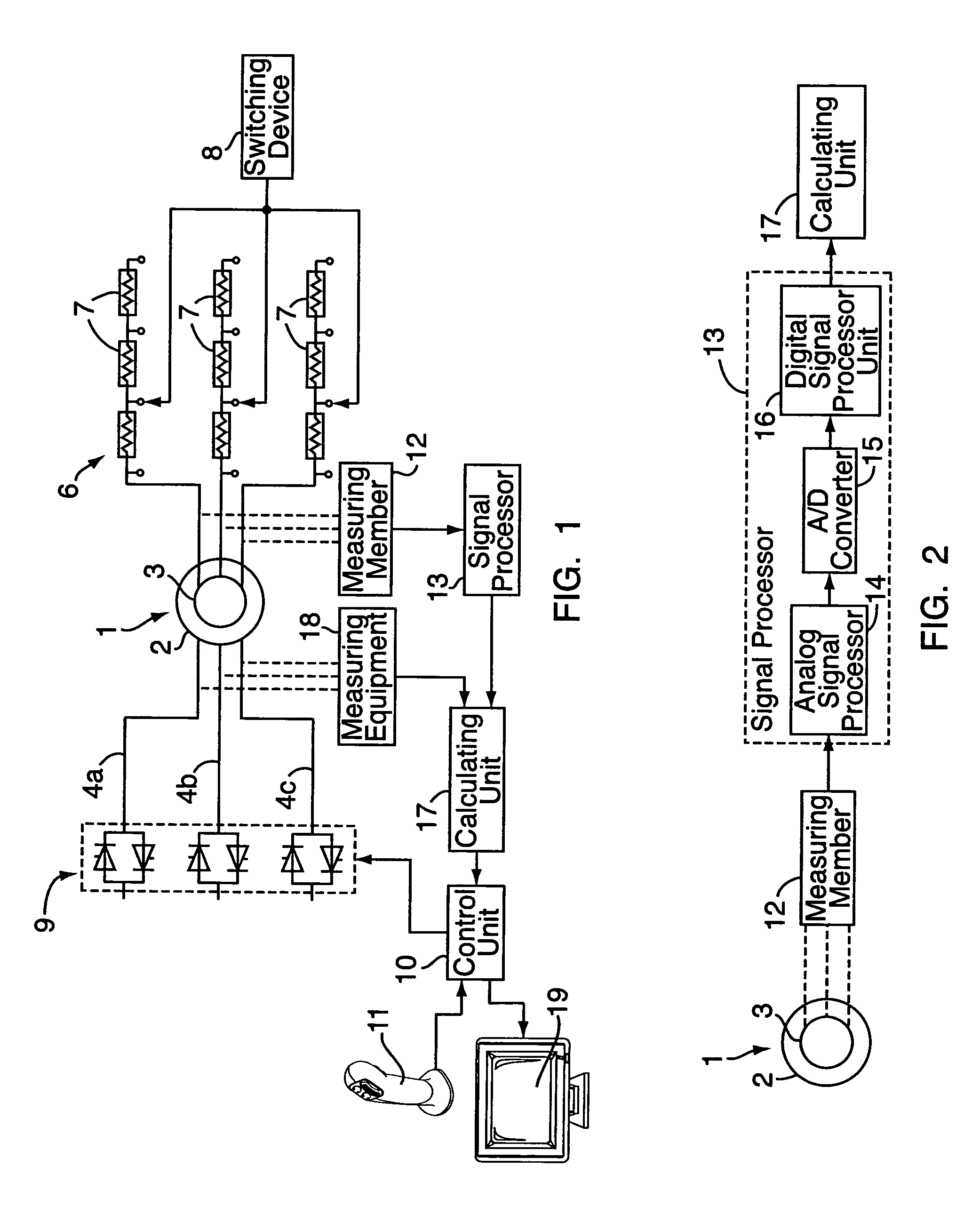
[0018]FIG. 1 shows schematically a control system using a device for estimation of the rotor speed of a slip ring asynchronous machine 1. Preferably, said control system may be used for controlling an arbitrary number of asynchronous machines, for examples, four asynchronous machines 1 in a crane. The asynchronous machine 1 comprises a stator 2 and a rotor 3. The stator 2 has a stator winding and the rotor 3 has a rotor winding. The asynchronous machine 1 is fed with three-phase voltage and current by cables 4a–c. The supplied three-phase voltage and current to the stator winding generates a varying magnetic flux, which induces a voltage in the rotor winding. The voltage in the rotor winding creates an electromagnetic torque, which drives the rotor 3 with a rotor speed with a slip in relation to a rotational speed of the varying magnetic flux. A circuit 6 including a plurality of resistors 7 is connected to each phase of the rotor winding. The circuits 6 include a desired number of ...


PUM


Abstract

The invention relates to a device and a method for estimating the speed of a slip ring asynchronous machine. The asynchronous machine includes a stator having a stator winding, arranged to be fed with three-phase voltage and current in order to generate a varying magnetic flux, and a rotor having a rotor winding in which the magnetic flux is arranged to induce a voltage to create an electromagnetic torque. The device includes a measuring member arranged to measure the value of the voltage in the rotor winding during at least one time period and a calculating unit, which is arranged, using the above measured voltage, to calculate a value of the rotor speed.

Description

CROSS-REFERENCE TO RELATED APPLICATIONS[0001]This application is entitled to the benefit of and incorporates by reference essential subject matter disclosed in International Application No. PCT / SE00 / 01980 filed on Oct. 12, 2000 and Swedish Patent Application No. 9903666-7 filed on Oct. 12, 1999.TECHNICAL FIELD OF THE INVENTION AND PRIOR ART[0002]The invention relates to a device and a method for estimating the speed of a slip ring asynchronous machine, wherein the asynchronous machine comprises a stator having a stator winding, arranged to be fed with three-phase voltage and current in order to generate a varying magnetic flux, and a rotor having a rotor winding in which the magnetic flux is arranged to induce a voltage to create an electromagnetic torque which drives the rotor with a rotor speed with a slip in relation to a rotation speed of the varying magnetic flux.[0003]Such slip ring asynchronous machines are used, for example, in cranes, rolling mills, in heavy industry and in...

Claims


Application Information

Patent Timeline
Patent Type & Authority Patents(United States)
IPC IPC(8): H02P27/04G01P3/44G01P3/48H02P23/00H02P27/02
CPCG01P3/48H02P7/00
Inventor HANSSON, LARS TUVESLUTEJ, ALOJZ
Owner ABB (SCHWEIZ) AG
Learn More