X-ray optical system with wobble device

a wobble device and optical system technology, applied in the field of xray optical system, can solve the problems of inability to detect the increase in the sweep sample region in reasonable measuring intervals, undesirable phenomena, and general undesirable phenomena, and achieve the effect of simple and effectiv

Active Publication Date: 2006-02-07
BRUKER AXS
View PDF7 Cites 11 Cited by
  • Summary
  • Abstract
  • Description
  • Claims
  • Application Information

AI Technical Summary

Benefits of technology

[0010]This object is achieved in a surprisingly simple but effective fashion with an X-ray optical system of the above-mentioned type by providing a wobble means for moving the X-ray optical element in an oscillating fashion during the measurement.

Problems solved by technology

This phenomenon, called the grain size effect, is generally undesirable.
This method is not applicable for many objects under investigation since they cannot be moved at all or only very slowly due to their large mass or high sensitivity to acceleration (e.g. for fluids) and therefore a noticeable increase in the swept sample region in reasonable measuring intervals is not possible.

Method used


Image

  • X-ray optical system with wobble device
  • X-ray optical system with wobble device
  • X-ray optical system with wobble device

Examples


Embodiment Construction

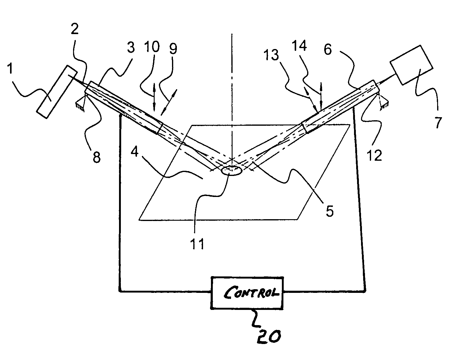
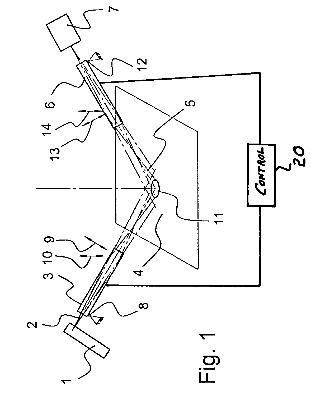
[0025]FIG. 1 shows a schematic representation of a first embodiment of an inventive X-ray optical system. An X-ray source 1 emits a diverging X-ray beam 2. It is focused by a first X-ray optical element 3, in the present case a monocapillary, and guided to a sample 4. The X-ray beam 2 interacts with the sample 4, and an X-ray beam 5 is emitted. It is focused by a second X-ray optical element 6, which is also formed as monocapillary, and directed onto an X-ray detector 7. The X-ray source 1 and X-ray detector 7 are disposed on one side of the sample 4, which is approximately flat (but must not necessarily be flat). This embodiment is therefore suited for measurements in reflection geometry.

[0026]The first X-ray optical element 3 is disposed at its end facing the X-ray source 1 on a ball-and-socket joint 8. The first X-ray optical element 3 can be pivoted (“wobbled”) through piezo elements (not shown) in an oscillating fashion in the direction of arrow 9 in the plane of the drawing or...


PUM

PropertyMeasurementUnit
diameteraaaaaaaaaa
diameteraaaaaaaaaa
angleaaaaaaaaaa

Abstract

An X-ray optical system comprising an X-ray source (1), from which X-ray radiation (2) is guided to a sample (4) under investigation, and an X-ray detector (7) for receiving radiation (5) diffracted or scattered from the sample (4), wherein a beam-guiding X-ray optical element (3, 6), such as e.g. a collimator, a mono- or polycapillary, an X-ray mirror or a monochromator, is disposed between the source (1) and the sample (4) and/or between the sample (4) and the detector (7), is characterized in that a wobble means is provided for moving the X-ray optical element (3, 6) in an oscillating fashion during the measurement. The inventive X-ray optical system obtains averaged X-ray analysis information from objects under investigation having large mass which consist of macrocrystalline material without destroying or accelerating the object under investigation.

Description

[0001]This application claims Paris Convention priority of DE 103 17 679.9 filed Apr. 17, 2003 the complete disclosure of which is hereby incorporated by reference.BACKGROUND OF THE INVENTION[0002]The invention concerns an X-ray optical system with an X-ray source from which X-ray radiation is guided to a sample to be examined, and an X-ray detector for receiving radiation diffracted or scattered from the sample, wherein a beam-guiding X-ray optical element, such as e.g. a collimator, a mono or poly-capillary, an X-ray mirror or a monochromator, is disposed between the source and the sample and / or between the sample and the detector.[0003]X-ray optical systems of this type are realized in almost all conventional X-ray diffractometers, e.g. in “ATX-G optical system”, The Rigaku Journal, Vol. 16, No. 1, 1999, pages 53–58.[0004]X-rays are used to examine the material properties of the most different kinds of samples. They can interact with the atoms of the sample in many ways, wherein ...

Claims


Application Information

Patent Timeline
Patent Type & Authority Patents(United States)
IPC IPC(8): G01N23/20G01N23/203
CPCG01N23/203G01N23/20
Inventor HELMING, KURTBRUGEMANN, LUTZ
Owner BRUKER AXS
Why Eureka
Try Eureka