Transmitter

a transmitter and transceiver technology, applied in the field of transceivers, can solve the problems of increasing the power efficiency of the transmitter, increasing the cost of the transmitter, so as to achieve the effect of less importance, relatively low cost, and reduced cos

Inactive Publication Date: 2006-02-07
NOKIA SIEMENS NETWORKS GMBH & CO KG
View PDF11 Cites 30 Cited by
  • Summary
  • Abstract
  • Description
  • Claims
  • Application Information

AI Technical Summary

Benefits of technology

[0018]Through the transmitter portrayed, a higher power efficiency is achieved and, through the extensive digitizing, the outlay for equalization of the analog circuit is relatively low. The essential nonlinearities of the transmission path are summarily compensated. A splitting ...

Problems solved by technology

Additional losses are low and the power efficiency of the transmitter is greater than in a carrier-related amplification.
Unlike in modulation methods with constant envelope, such as the GMSK modulation for GSM mobile ...

Method used


Image

  • Transmitter
  • Transmitter
  • Transmitter

Examples


Embodiment Construction

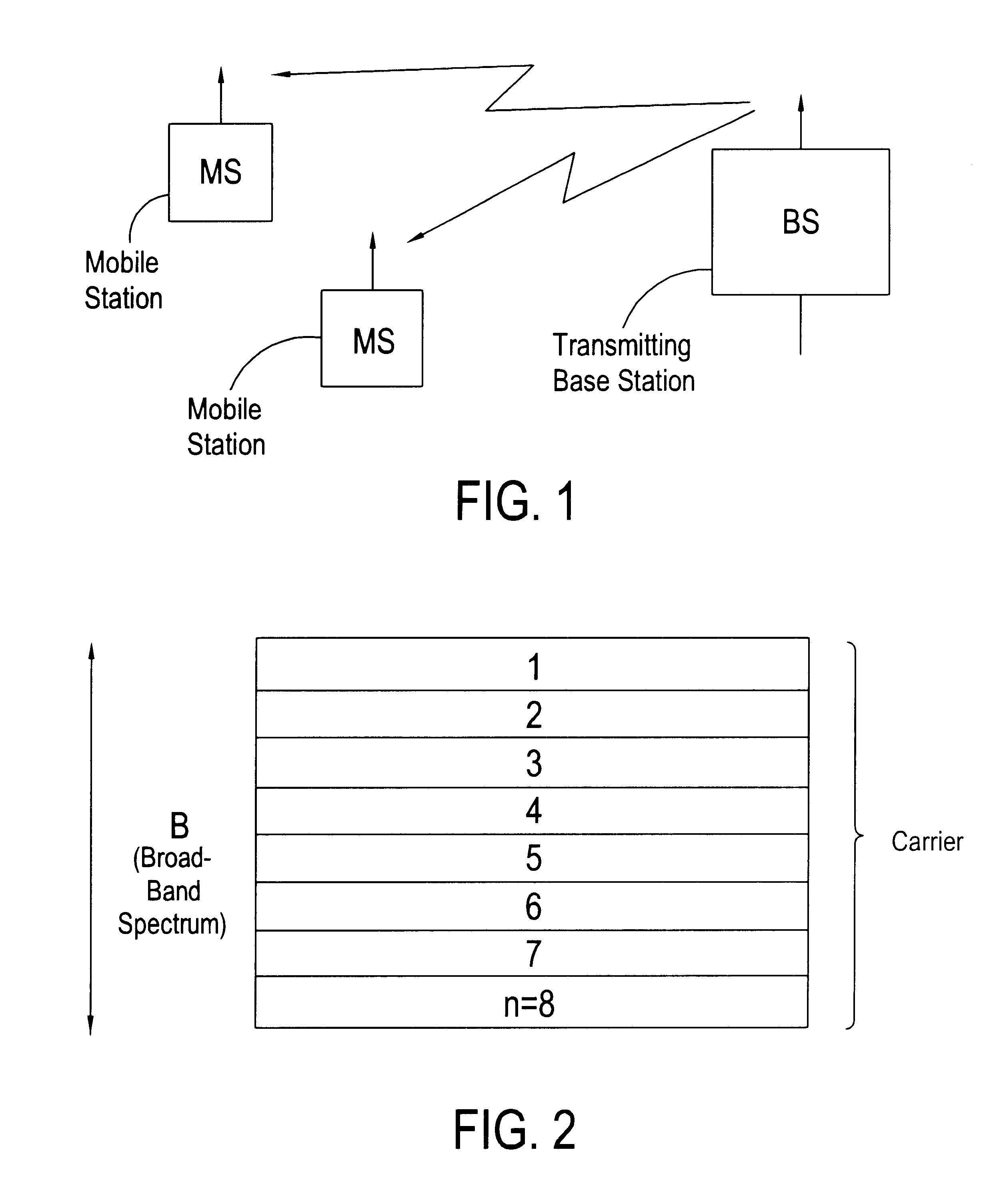
[0024]FIG. 1 shows the information transmission from a transmitting base station BTS to mobile stations MS. The base station BTS contains a transmitter which creates a broad-band transmission signal. The broad-band transmission signal includes a spectrum B, for example B=1.6 MHZ, in which a plurality of carriers 1, 2, . . . , n=8 (see FIG. 2) are simultaneously contained. Two mobile stations MS can thus be served on different carriers simultaneously, for example.

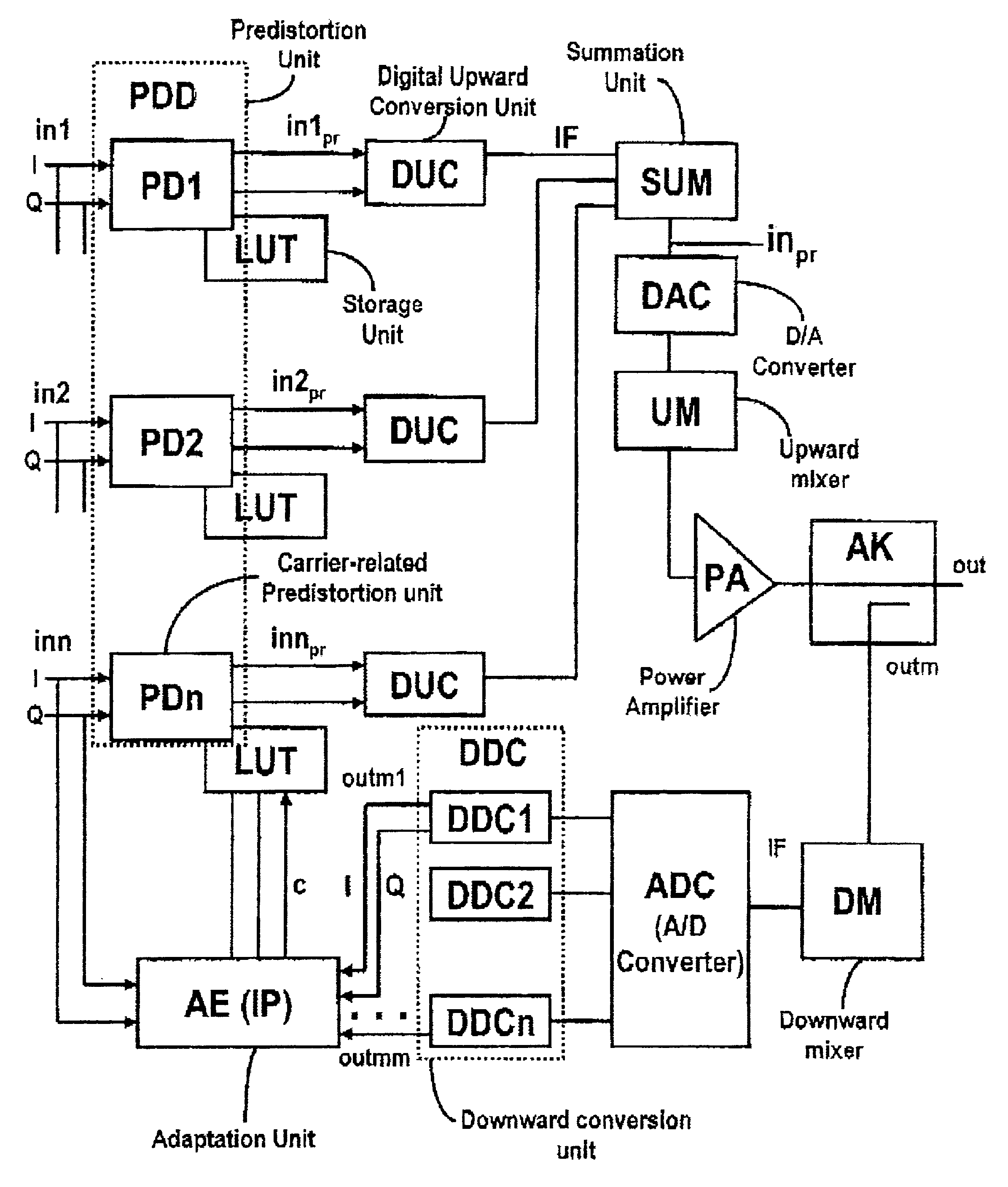
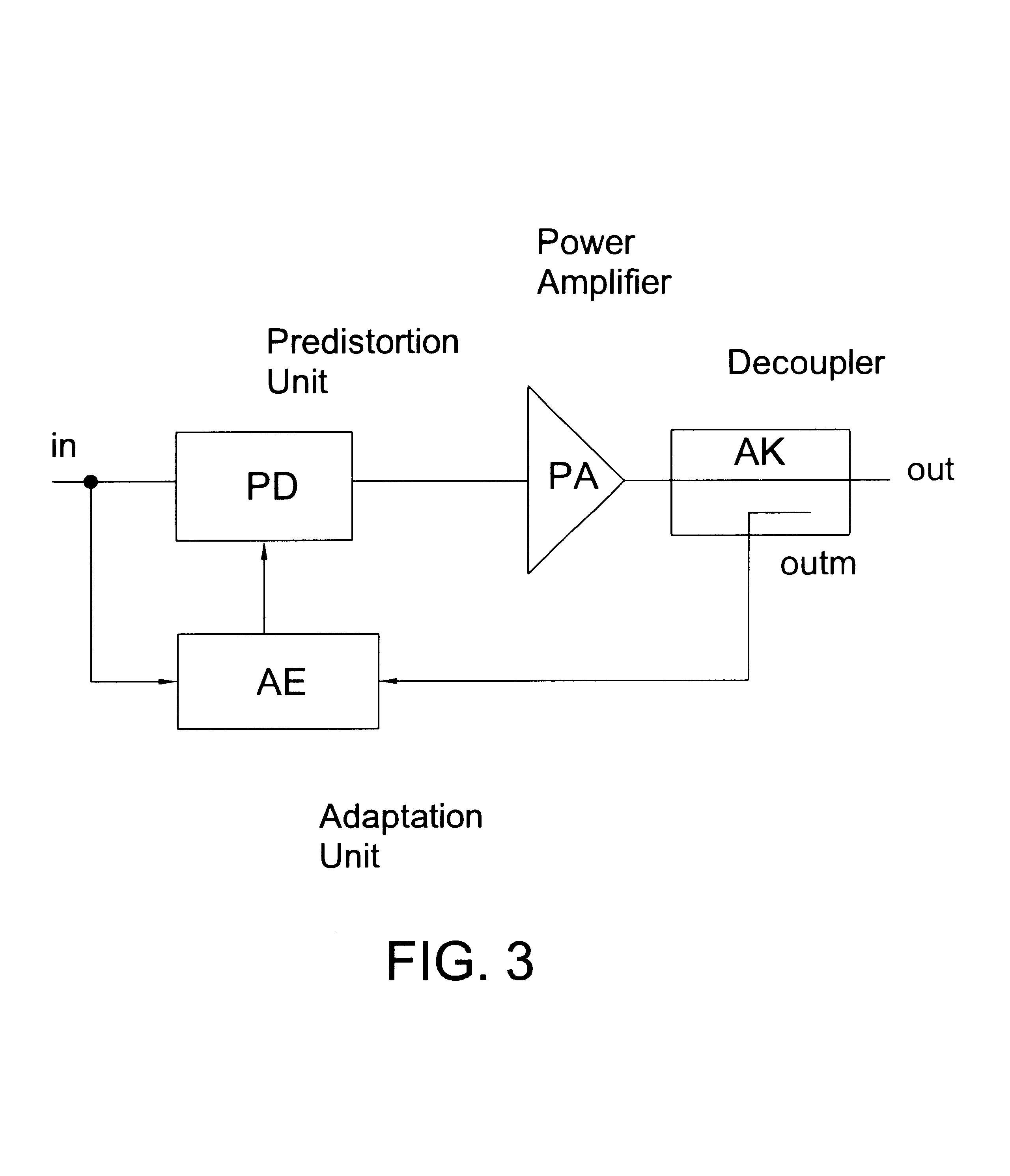
[0025]FIG. 3 shows a block wiring diagram of the transmitter which contains a predistortion unit PD, a power amplifier PA, a decoupler AK and an adaptation unit AE. An input signal in is fed to the predistortion unit PD and to the adaptation unit AE. The predistortion unit PD performs a predistortion of the input signal in whereby setpoint selections of a correction signal c created by the adaptation unit AE are followed. The predistorted input signal is amplified in the power amplifier PA, whereby the distortion of the powe...


PUM


Abstract

A transmitter for a plurality of carriers of a broad-band transmitting spectrum which contains a broad-band power amplifier encompassing the carriers for amplifying an input signal into a more powerful output signal, wherein a measuring signal is formed from the output signal with the aid of a decoupler. The transmitter further contains an adaptation unit for comparing the input signals to the measuring signals and for thereafter forming a correction signal. A predistortion of the input signal is performed in a predistortion unit in the transmitter corresponding to the setpoint selections of the correction signal.

Description

BACKGROUND OF THE INVENTION[0001]1. Field of the Invention[0002]The present invention relates to a transmitter for a plurality of carriers of a broad-band transmission spectrum.[0003]2. Description of the Prior Art[0004]Transmitters of the afore-mentioned type are preferably utilized in radio stations within mobile radio networks in which a transmission of information to further radio stations occurs in a plurality of carriers with the aid of radio-frequency signals. These radio stations are base stations which are stationary and which carry out information transmission to mobile stations, for example. In a transmitter, input signals are amplified into more powerful output signals and are converted into a corresponding transmitting frequency.[0005]If a broad-band transmitting spectrum with a plurality of carriers is amplified, linearity problems of amplification arise. In order to keep the power efficiency of the power amplifier within the transmitter high, the latter is usually ope...

Claims


Application Information

Patent Timeline
IPC IPC(8): H04B1/02H04B1/10H03F1/32
CPCH03F1/3247H03F2201/3233H03F2201/3206H03F2200/57
Inventor HELMS, JOCHEN
Owner NOKIA SIEMENS NETWORKS GMBH & CO KG
Why Eureka
Try Eureka