Graphical user interface for a transport multiplexer

a transport multiplexer and user interface technology, applied in data switching networks, selective content distribution, instruments, etc., can solve the problems of inefficient and expensive purchase and operation, difficult to utilize systems, and difficult to configure routing control, etc., to simplify operation, simplify routing control, and simplify the effect of configuration routing control

Inactive Publication Date: 2006-02-07
GOOGLE TECHNOLOGY HOLDINGS LLC
View PDF22 Cites 57 Cited by
  • Summary
  • Abstract
  • Description
  • Claims
  • Application Information

AI Technical Summary

Benefits of technology

[0017]The present invention satisfies the above-stated needs and overcomes the above-stated and other deficiencies of the related art by providing methods, systems and apparatus that enables real-time monitoring and manipulation of content streams flowing through a transport multiplexer. The invention can take the form of a graphical user interface capable of displaying system hardware identity, structure, configuration and / or status information. The interface can also provide computer assisted routing configuration through simple manipulation of graphical objects such as drag and drop operations performed on icons. To further simplify operation, the invention has the ability to display intuitive and consistent mnemonic identifiers for the various content streams that are displayed on various screens throughout the graphical user interface. Routing control is further simplified by permitting operators to configure routing control of individual content stream components as well as groups of such components simultaneously. Still further flexibility is provided by configuration of future routing events, thereby enabling the automatic execution of configuration changes at a future time.

Problems solved by technology

Broadband media convergence between video, audio and data creates a chaotic environment of different standards and legacy communications technologies.
For these and other reasons, most of such systems are nearly intolerably difficult to utilize, counter-intuitive, cryptic, inefficient and expensive to purchase and operate.
Another problem with conventional broadband communications hardware is its inability to conveniently provide operators with information regarding the system hardware and software.
This creates many inefficiencies in operation of such equipment.
As but one example, troubleshooting system errors is currently a difficult and expensive process because system operators must physically inspect the broadband communications hardware in order to determine the system hardware utilized and its operational status.
In particular, troubleshooting system difficulties may entail operator inspections of a communications hardware rack to determine if all of the communications hardware has been plugged-in, turned on, connected to a source of content stream and / or operating in a particular way.
In addition to the difficulties associated with determining hardware configuration and status, conventional broadband communications hardware makes it difficult to determine current content stream routing configurations.
This is, in part, due to the fact that current broadband communications hardware is not sophisticated enough to indicate various attributes of incoming data streams.
The difficulties associated with conventional methods of routing control make it extremely difficult to efficiently utilize system bandwidth.
Therefore, operators of conventional systems of this nature often underutilize the bandwidth available to perform content stream routing.
Given that transport bandwidth is still a precious commodity in this field, this is a significant deficiency.
A further deficiency associated with conventional broadband communications hardware is that such hardware must be manually configured.
As the demand for information / content options continues to increase, it becomes increasingly difficult to manually configure broadband communications hardware to route content streams.

Method used


Image

  • Graphical user interface for a transport multiplexer
  • Graphical user interface for a transport multiplexer
  • Graphical user interface for a transport multiplexer

Examples


Embodiment Construction

[0034]The ensuing detailed description provides preferred exemplary embodiments only, and is not intended to limit the scope, applicability, or configuration of the invention. Rather, the ensuing detailed description of the preferred exemplary embodiments will provide those skilled in the art with an enabling description for implementing a preferred exemplary embodiment of the invention. It being understood that various changes may be made in the functional arrangement of elements without departing from the spirit and scope of the invention as set forth in the appended claims.

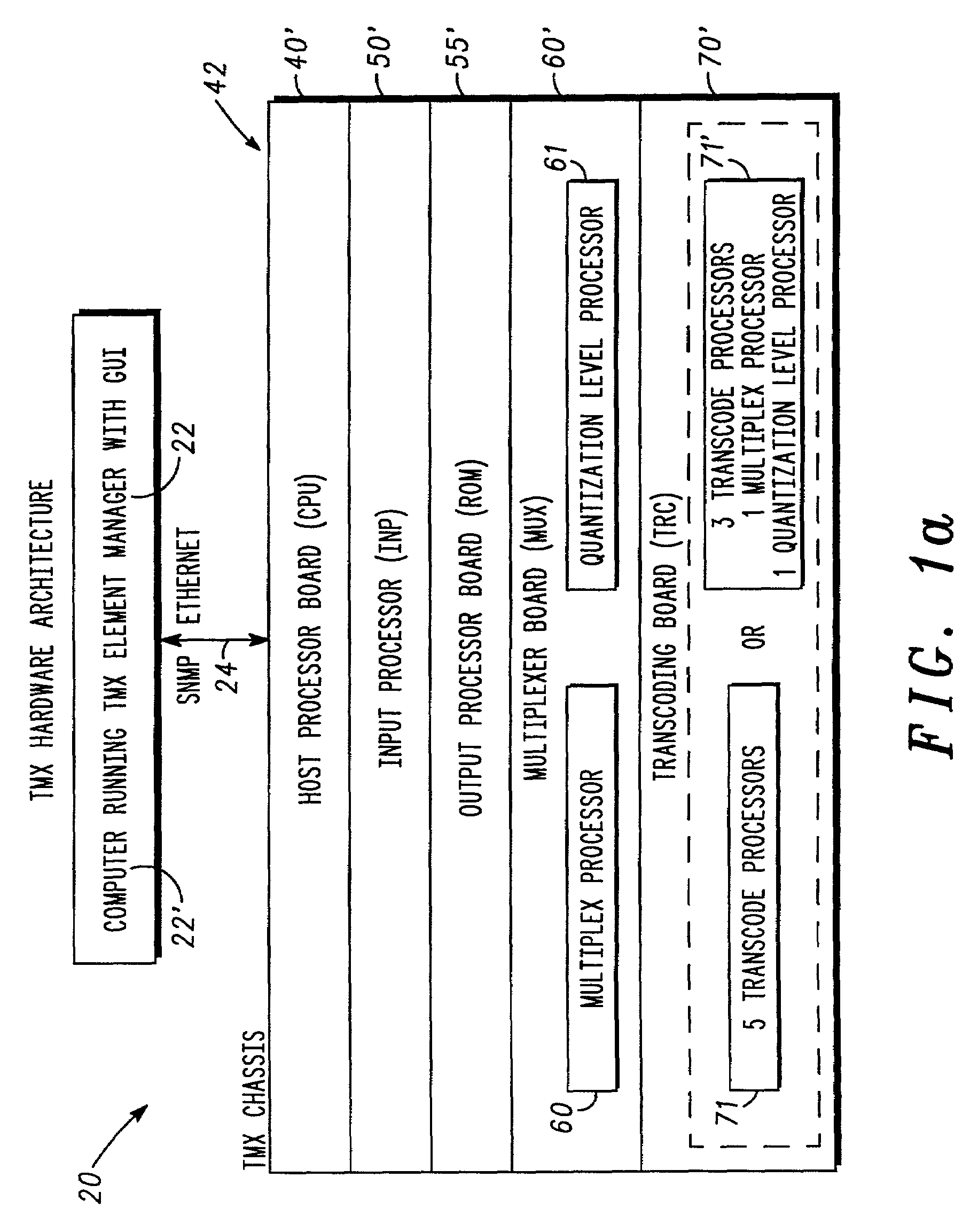
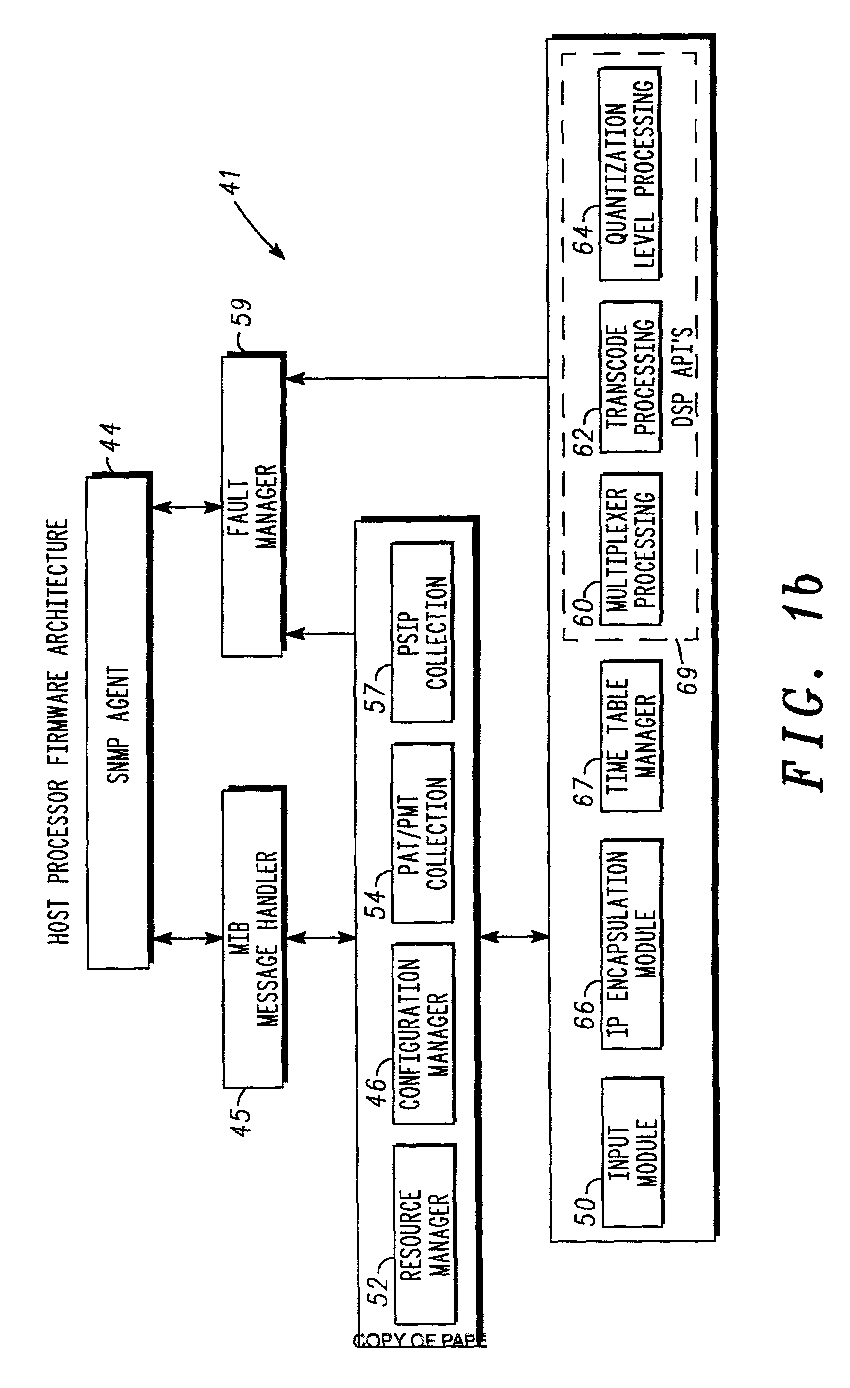
[0035]As shown in FIGS. 1a and 1b, TMX 20 includes a plurality of hardware, firmware and software components. FIG. 1a is a hardware architecture diagram showing a representative transport multiplexer (TMX) 20 in accordance with one preferred embodiment of the present invention. As shown therein, the transport multiplexer can include, for example, a computer 22′ (with an element manager 22 and a GUI 80) that is ...


PUM


Abstract

A feature-rich transport multiplexer and a number of associated methods, systems, subsystems, software features, graphical user interfaces and control systems are disclosed. The disclosure includes GUI's that enable operators to easily monitor and manipulate content streams flowing through a transport multiplexer in real-time. The disclosed interfaces include screens that supply operators with identity, structure, configuration, bandwidth utilization and / or status information for system hardware and software. The disclosed features also provide computer assisted routing configuration for present and future routing events through simple manipulation, such as drag and drop operations, of graphical objects. Routing control is further simplified by permitting operators to configure routing control of individual content stream components as well as groups of such components simultaneously. Further flexibility is permitted by predetermination of future routing events, thereby enabling the automatic execution of configuration changes at a future time. Various types of content, such as video, audio, IP data can be manipulated to achieve various results such as one or more multiplexed MPEG data streams.

Description

CROSS REFERENCE TO RELATED CASES[0001]This application claims the benefit under 35 U.S.C. 1 19(e) of co-pending U.S. Provisional Application Nos. 60 / 285,188 filed Apr. 20, 2001 and entitled “Broadband Bandwidth Management, Device Management and Multi-Media Control System”; and 60 / 285,153 filed Apr. 20, 2001 and entitled “Data Insertion, Transport, Grooming, Aliasing, Routing, and Multiplexing of MPEG 2 Data Streams”, which Provisional Applications are hereby incorporated by reference.[0002]This application is related to U.S. patent application Ser. No. 10 / 124,610, filed Apr. 16, 2002 (based on provisional application No. 60 / 322,063 filed Sept. 13, 2001) and entitled “High Speed Serial Data Transport Between Communications Hardware Modules,” which Application is hereby incorporated by reference.[0003]This application hereby incorporates by reference a computer program listing submitted concurrently herewith on two duplicate compact discs pursuant to the provisions of 37 C.F.R. § 1.52...

Claims


Application Information

Patent Timeline
Patent Type & Authority Patents(United States)
IPC IPC(8): G06F3/00H04L12/18H04L12/24H04L12/26H04L29/06H04L29/08H04N7/24H04N7/52
CPCH04L12/18H04L29/06027H04L41/0213H04L41/046H04L41/0896H04L41/22H04L43/00H04L43/0817H04N7/52H04N21/235H04N21/23614H04N21/2365H04N21/4347H04N21/4348H04N21/435H04N21/6433H04L67/16H04L67/36H04L29/06H04L69/329H04L41/0253H04L41/06H04L43/045H04L43/0888H04L2212/0025H04L69/22H04L2212/00H04L67/51H04L67/75H04L9/40H04L65/1101
Inventor MEANDZIJA, BRANISLAV N.HEWETT, JEFF H.TSAY, YING YING
Owner GOOGLE TECHNOLOGY HOLDINGS LLC
Why Eureka
Try Eureka