Deployable bullets

Inactive Publication Date: 2006-02-14
OMNITEK PARTNERS LLC
View PDF11 Cites 23 Cited by
  • Summary
  • Abstract
  • Description
  • Claims
  • Application Information

AI Technical Summary

Benefits of technology

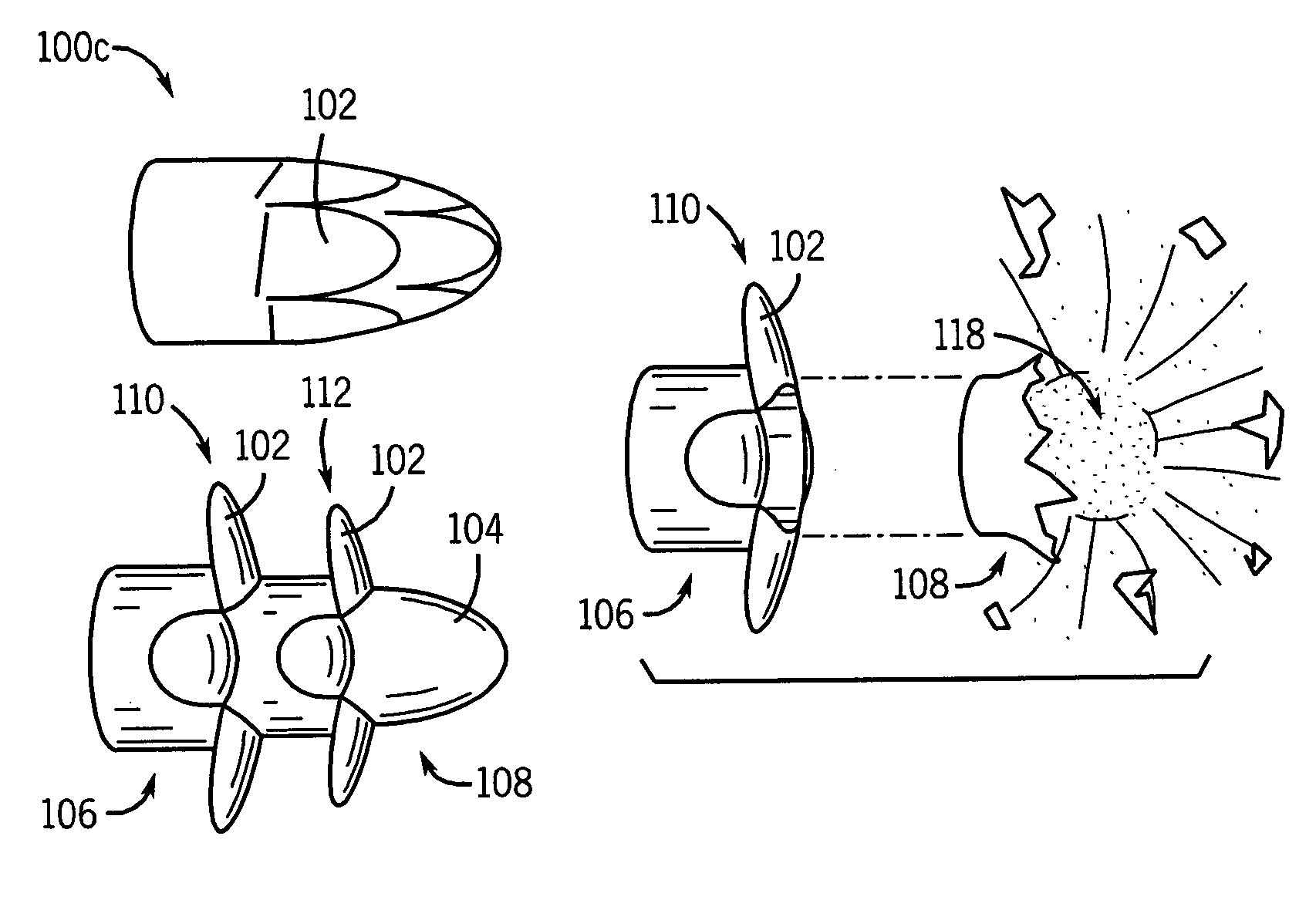
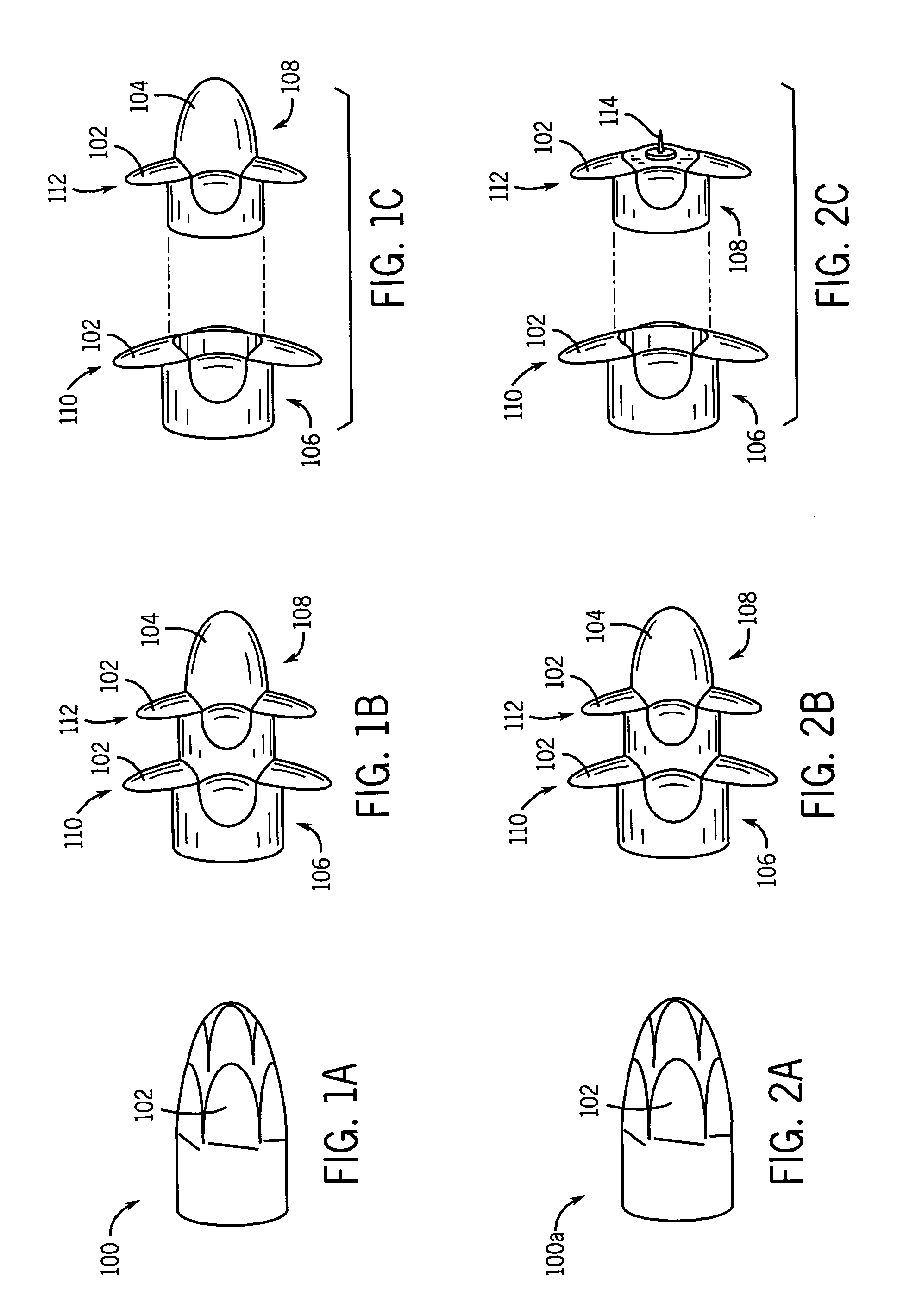
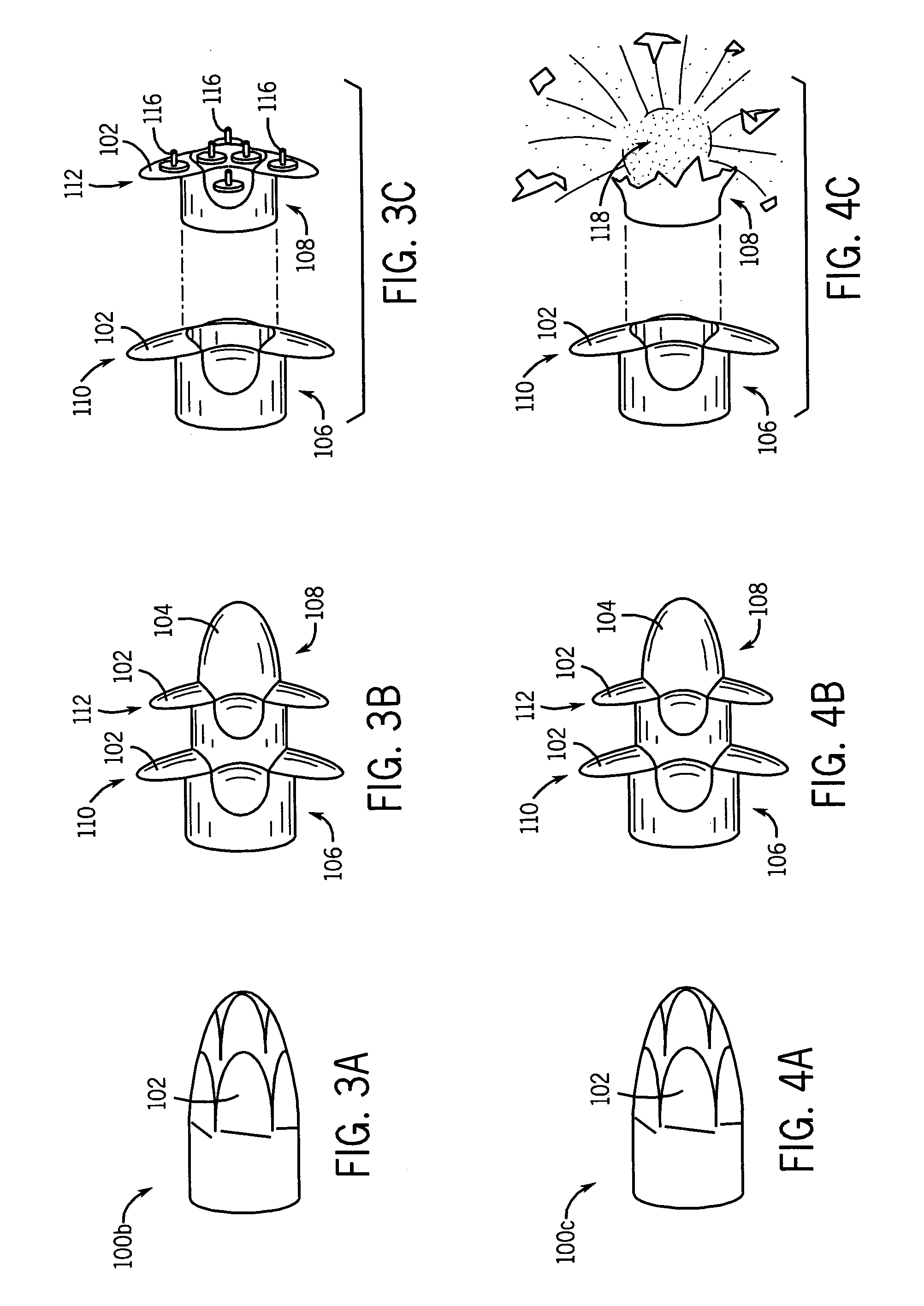
[0009]An objective of the present invention is to provide novel bullets that have deployable blades or o

Problems solved by technology

Rubber type bullets are also used in delicate environments, such as on aircraft, where a regular bullet may compromise the pressurized environment inside the aircraft cabin.
There are significant flaws in the designs of all these types of personal security tools.
Modern day rubber bullets still kill to often and are only effective if they target and impact a per

Method used


Image

  • Deployable bullets
  • Deployable bullets
  • Deployable bullets

Examples


Embodiment Construction

[0030]In operation, a bullet of the present invention is fired from a small or medium caliber gun barrel. The bullet is generally constructed with deployable blades or other deployable portions which act to reduce the momentum of the bullet. As discussed below, the blades or other deployable portion of the bullet can be spring loaded and deployed after exiting the gun barrel. Preferably, the blades or other deployable portion of the bullet are deployed, at least partially, by the centrifugal force on the deployable portion due to the spinning of the bullet when it exits the gun barrel. In both preferred implementations, as discussed below, the blades or other deployable portion can have a weakened portion acting as a living hinge to aid in the deployment of the blades or other deployable portion. Furthermore, due to the airflow around the bullet, once the blades or other deployable portion begins to deploy, the airflow against the same will also aid in their deployment.

[0031]At an o...


PUM


Abstract

A method for non-lethal crowd and personal protection. The method includes: firing non-lethal bullets towards a person; and deploying portions on the non-lethal bullets prior to impacting the person to decrease its impact pressure on the person.

Description

CROSS-REFERENCE TO RELATED APPLICATIONS[0001]This application claims priority to earlier filed U.S. provisional application Ser. No. 60 / 317,308 filed on Sep. 5, 2001, the entire contents of which is incorporated herein by its reference. This application is related to co-pending application Ser. No. 10 / 236,004 filed on the same day herewith entitled “Deployable Projectiles” the contents of which are incorporation herein by its reference.BACKGROUND OF THE INVENTION[0002]1. Field of the Invention[0003]The present invention relates generally to bullets, and more particularly, to bullets, which have deployable blades or other portions thereof to increase the footprint of the bullet and / or decrease the momentum of the bullet.[0004]2. Prior Art[0005]The first less-than-lethal bullets appeared in the 1880s when Singapore police shot sawed-off broom handles at rioters. By the 1960s, riot control police in Singapore, Malaysia, and Hong Kong were using more sophisticated wooden bullets. Britis...

Claims


Application Information

Patent Timeline
IPC IPC(8): F42B12/46F42B10/02F42B30/02F41J2/00F42B10/14F42B12/34H01M2/02H01M2/10H01M10/40H01M12/06
CPCF41J2/00F42B12/46F42B12/34F42B10/14
Inventor RASTEGAR, JAHANGIR S.
Owner OMNITEK PARTNERS LLC
Why Eureka
Try Eureka