Apparatus for controlling traffic flow along a pathway

a technology for controlling traffic flow and traffic pathways, applied in the direction of traffic gates, ways, transportation and packaging, etc., can solve the problems of increasing maintenance costs, not being able to meet the requirements of traffic flow, so as to achieve economic manufacturing and minimal maintenance

Inactive Publication Date: 2006-02-14
ZARKADES NICHOLAS
View PDF17 Cites 11 Cited by
  • Summary
  • Abstract
  • Description
  • Claims
  • Application Information

AI Technical Summary

Benefits of technology

[0015]Another object of this invention is to provide an extendible gate that is reliable and economical to construct.
[0017]Yet another object of this invention is to provide a railroad crossing gate that is economical to manufacture.
[0018]Still another object of this invention is to provide a railroad crossing gate that is reliable and requires minimal maintenance.

Problems solved by technology

This approach is effective, but it also is expensive because it requires twice the number of gates with all their structures and costs and twice the maintenance.
Further, upgrading existing crossings still require a significant effort in routing utilities either across the highway or beneath the tracks in order to control the operation of the two additional gates.
In many situations, however, this is not possible because the position of the gate in an open, or vertical, position may interfere with trees, power lines or other structures proximate the crossing gate location.
However, they all require increased maintenance.
Each operating mechanism is subject to wear and vandalism.
The motor-driven railroad crossing gates are more expensive to manufacture and still require further maintenance.
However, each of the foregoing operating mechanisms has inherent complexities and costs that will make the use of such operating mechanism unattractive for retrofitting.

Method used


Image

  • Apparatus for controlling traffic flow along a pathway
  • Apparatus for controlling traffic flow along a pathway
  • Apparatus for controlling traffic flow along a pathway

Examples


Embodiment Construction

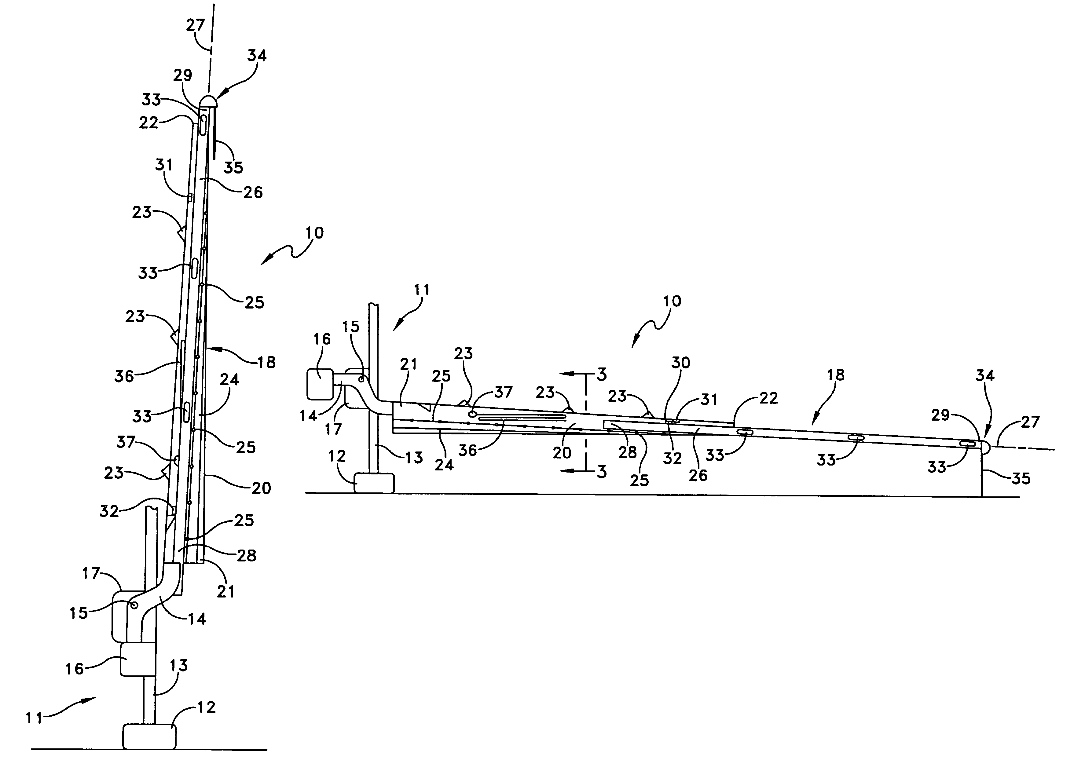
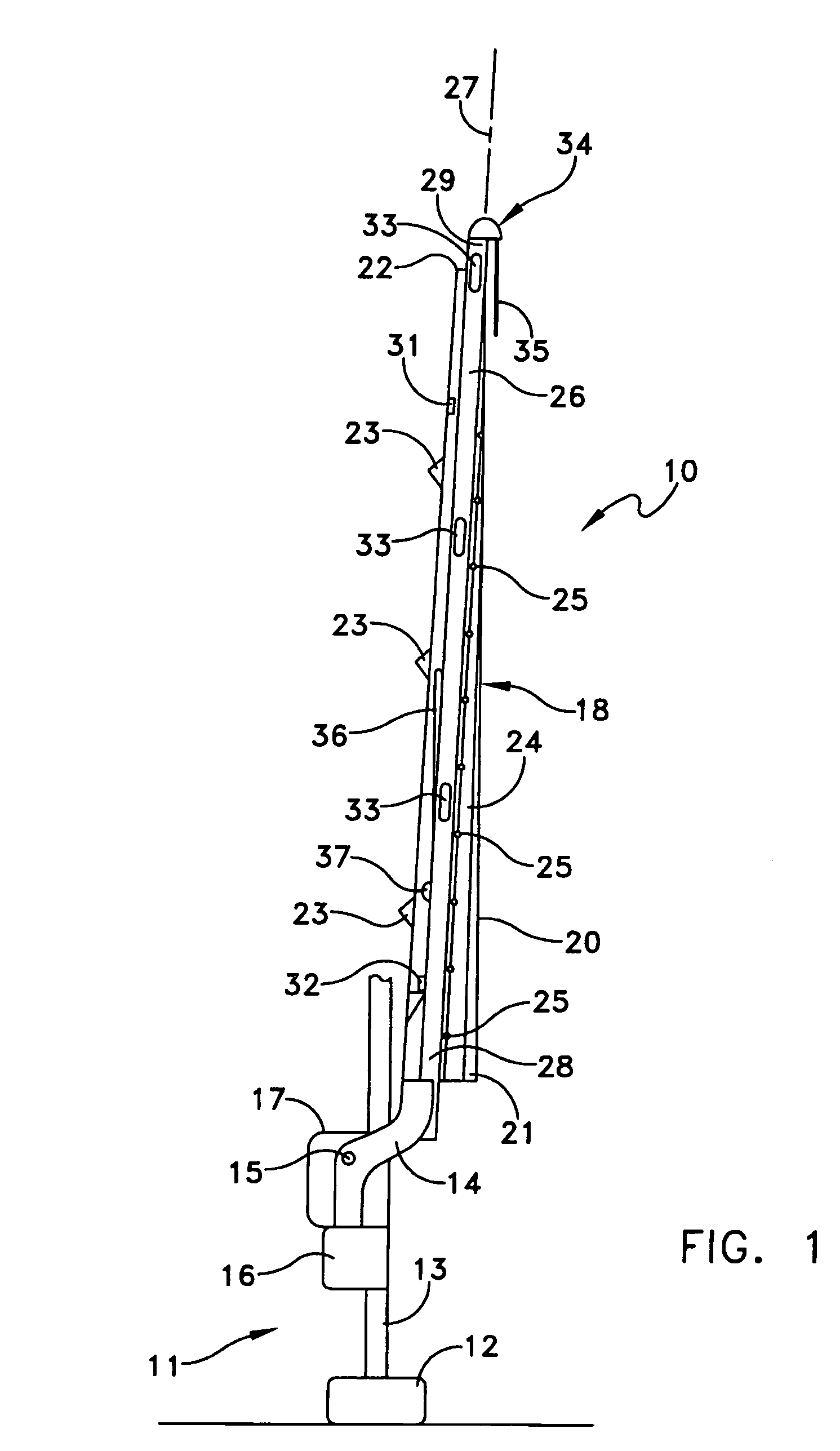
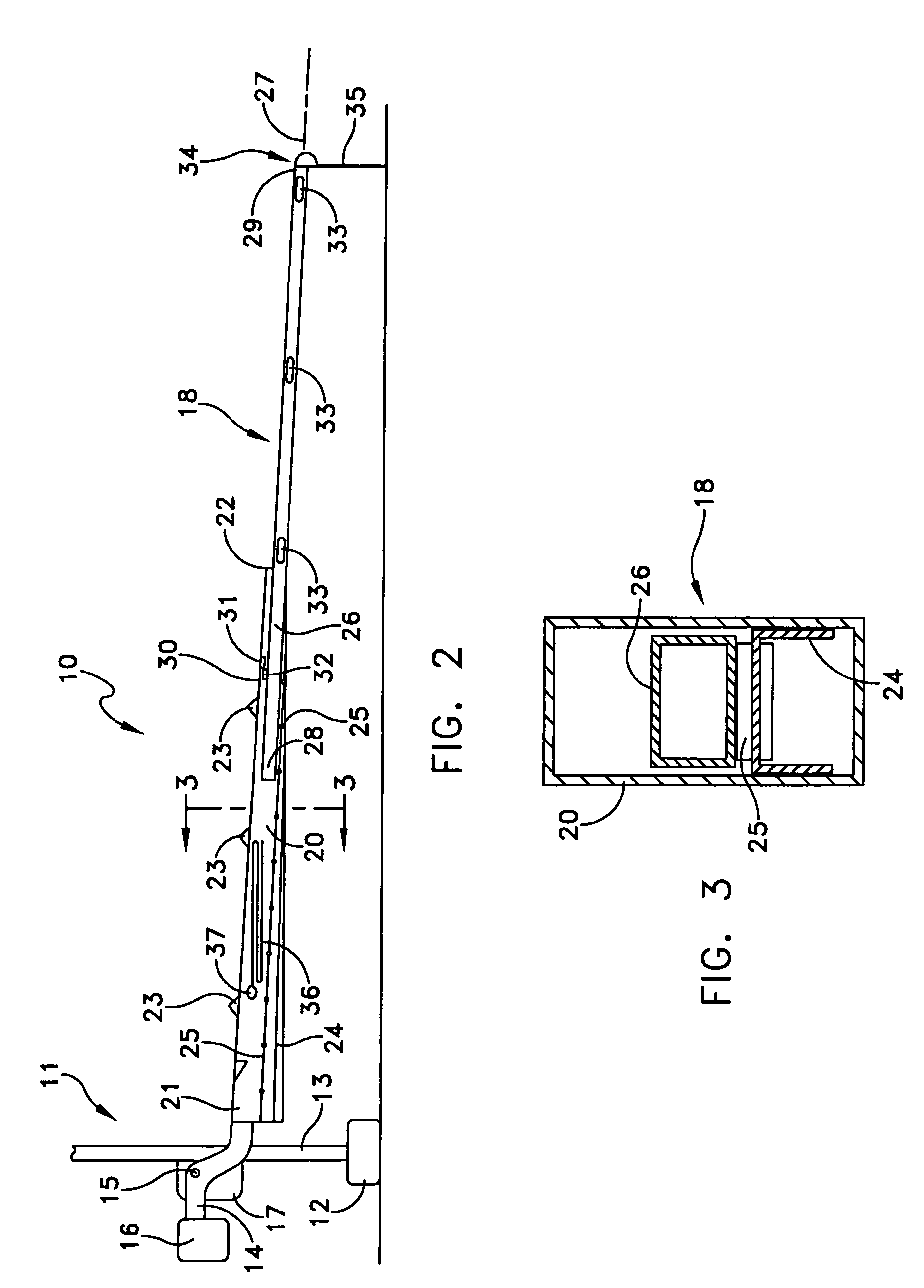
[0031]Referring to FIGS. 1 through 3, a first embodiment of a crossing gate 10 includes a base unit 11 with a base or footing 12 generally buried in the ground. A post 13 extends vertically from the footing 12 and carries a rotatable arm 14 mounted on a pivot 15 with a counterweight 16. An enclosed motor drive 17 moves the arm 14 between an open position shown in FIG. 1 and a closed position shown in FIG. 2. Such base units 11 are well-known in the art and are particularly adapted for being retrofitted by a gate constructed in accordance with this invention.

[0032]The arm 14 carries a gate 18 constructed in accordance with this invention. In FIGS. 1 through 3, the gate 18 includes a first hollow member 20 with a first an end 21 affixed to the arm 14. A second end 22 typically will be displaced from the first end 21 so the overall length of the first member will be approximately one-half the width of a grade crossing. That is, in the blocking position shown in FIG. 2, the first member...


PUM


Abstract

A railroad crossing gate with a gate assembly. An extendible member slides within an outer member with minimal friction. When the gate is in its open position, gravity retracts the extendible member to hollow member. When the gate is in its blocking position, gravity causes the extendible member to move out of the hollow member to a final blocking position.

Description

BACKGROUND OF THE INVENTION[0001]1. Field of the Invention[0002]This invention generally relates to devices for blocking the flow of traffic along a traffic pathway and more specifically to gates that control automotive flow at a highway railroad crossing.[0003]2. Description of Related Art[0004]Efforts are being made to improve safety at railroad gate crossings. The purpose is to prevent collisions between trains and automotive vehicles. Conventional crossing gates comprise two crossing gate assemblies. One gate is positioned on each side of the railroad crossing. When the gate is in a blocking position it blocks only the approach lane or lanes of a highway, not the exit lanes. So it is possible for a person to cross the tracks with the gates in their blocking positions.[0005]More recently it has been suggested to use four crossing gates. A pair of gates are positioned on each side of the highway. One gate closes the approach lane and the other the exit lane. As a result the gates ...

Claims


Application Information

Patent Timeline
Patent Type & Authority Patents(United States)
IPC IPC(8): B61L29/00B61L29/04
CPCB61L29/04
Inventor ZARKADES, NICHOLAS
Owner ZARKADES NICHOLAS
Why Eureka
Try Eureka