Method and apparatus for forming dye sublimation images in solid plastic

a technology of solid plastic and sublimation image, which is applied in the direction of dyeing process, transportation and packaging, etc., can solve the problems of plastic flaking or peeling, plastics that are not suitable for permanent imaging, and imaging technologies suitable for use on other materials, which have not generally met with success when used to perform permanent imaging plastics, etc., to achieve superior dye sublimation imaging and prevent unwanted adhesion of dye carriers

Inactive Publication Date: 2006-02-14
SEKISUI KYDEX LLC
View PDF24 Cites 60 Cited by
  • Summary
  • Abstract
  • Description
  • Claims
  • Application Information

AI Technical Summary

Benefits of technology

[0028]In order to attain these advantages, the present invention teaches a method wherein a substrate is disposed on a perforated platen and a dye carrier having an image formed thereon of a dye sublimation ink is disposed on the substrate such that the image is in contact with the substrate. The substrate, dye carrier, and at least a portion of the perforated platen are then covered with a flexible membrane. A uniform clamping pressure is then applied to the substrate and the dye carrier. One means of attaining this uniform clamping pressure is by inducing a pressure differential between the ambient atmosphere and the atmosphere under the membrane. Once the clamping pressure is attained, the substrate and dye carrier are first heated to a temperature sufficient to effect the dye sublimation imaging and retained at that temperature for a period of time sufficient to cause the imaging, then they are cooled to a point where the substrate again becomes rigid. The heating and cooling taught herein effect a first and a second thermal event, both performed while the substrate is under clamping pressure. The first and second thermal events, in operative combination, not only form the image and preclude the unwanted warping, twisting, or shrinkage of the substrate, but also preclude the unwanted adhesion of the dye carrier to the substrate.
[0029]The invention disclosed herein further teaches a number of novel apparatuses to effect the method, resulting in significantly superior dye sublimation imaging than heretofore attainable.

Problems solved by technology

Prior imaging technologies suitable for use on other materials, for instance metals, wood, and the like, have not generally met with success when used to perform permanent imaging plastics.
In general the problems associated with utilizing prior imaging or marking technologies center on certain chemical and physical properties of plastics in general.
While this is an advantage in the manufacture of such plastic objects, the extremely smooth and often chemically resistant nature of plastic surfaces renders the application thereto of paints and the like less than satisfactory.
Many paints, for instance enamels, when applied to plastics tend to flake or peel when the plastic is flexed or when the image is subjected to physical distress such as abrasion or temperature change.
While surface-formed images are completely suitable for many applications, they are less than optimal for others.
However, where it is desirous that the resultant article has a lustrous or translucent property, the use of such opaque inks precludes the desired translucent image.
The lack of success on the part of other inventors in this field is largely due to the fact that while the inventions disclosed in the previously discussed patents may theoretically be capable of implementation, in actual practice their use has failed to produce imaged flat plastic sheets at commercially acceptable costs or in commercially acceptable volumes.
The first reason that many known processes have not resulted in commercially successful imaged articles is that they are slow.
An imaging process which requires an extended period of time to successfully form an image, or which requires a large number of complex and delicate steps to effect, may result in a successfully imaged flat plastic sheet, but one whose imaging is so expensive as to render it commercially non-viable.
Moreover, previous imaging processes are so sensitive to temperature variations that very slight changes in processing temperatures result in unacceptable images or destroyed substrates.
In many cases this results in substantial liquefaction of the substrate, with attendant unwanted adhesion of the dye carrier to the now liquefied and sticky substrate.
Even where it is possible to scrape the adhered dye carrier from the cooled substrate, this scraping not only results in a poor surface finish, but also requires significant cost in terms of additional man-hours to effect.
The introduction of such parting or separating materials may preclude, in some instances, the unwanted adhesion of the dye carrier to the substrate, but this is done with significant degradation of the imaged article.
These methodologies are admitted to cause degradation in surface finish, image resolution, or image registration on the substrate.
Finally, and most importantly, when applied to solid plastic sheets, known dye sublimation imaging processes tend to shrink, warp and distort those sheets.
While the degree of shrinkage, warping, and distortion varies from process to process and substrate to substrate, these defects encountered utilizing known dye sublimation imaging technologies result in anything from mildly rumpled surfaces to wildly distorted sheets having all the planarity of potato chips.
Since the object of dye sublimation imaging of solid plastic sheets is to form an image within the sheet while retaining its substantially planar nature in an un-shrunken, un-warped and distortion-free state, none of the known processes can be said to be fully successful.
Moreover, one or more of the technical performance specifications of plastic sheets imaged by other dye sublimation processes are often lost be subjecting the sheets to the process.

Method used


Image

  • Method and apparatus for forming dye sublimation images in solid plastic
  • Method and apparatus for forming dye sublimation images in solid plastic
  • Method and apparatus for forming dye sublimation images in solid plastic

Examples


Embodiment Construction

[0048]The succeeding discussion centers on one or more preferred embodiments of the present invention, implemented by a number of components. Those having skill in the art will understand that where the embodiments enumerated herein specify certain commercially available components, these are by way of example. The principles of the present invention are capable of implementation in a wide variety of configurations and these principles specifically contemplate all such embodiments.

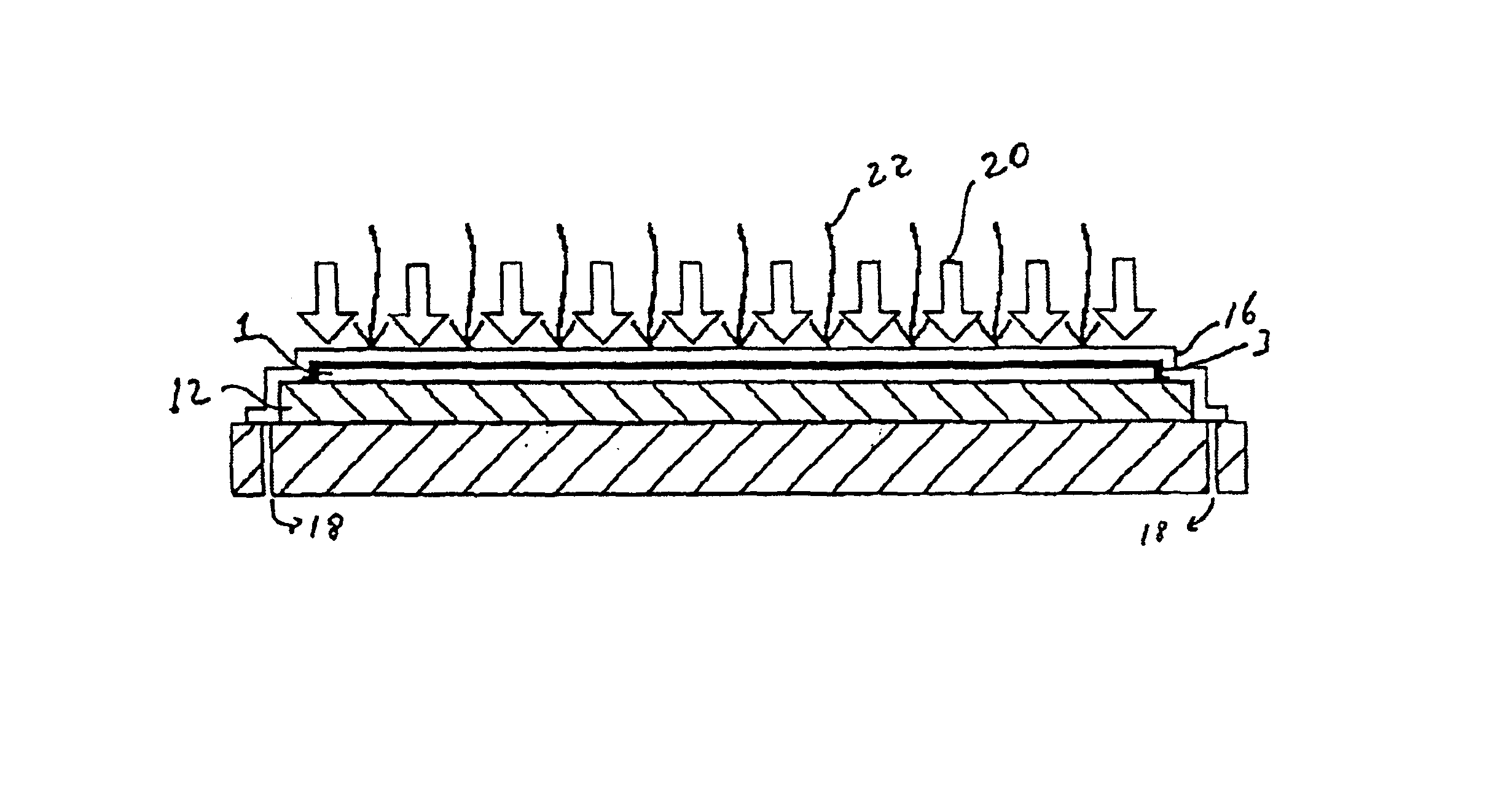
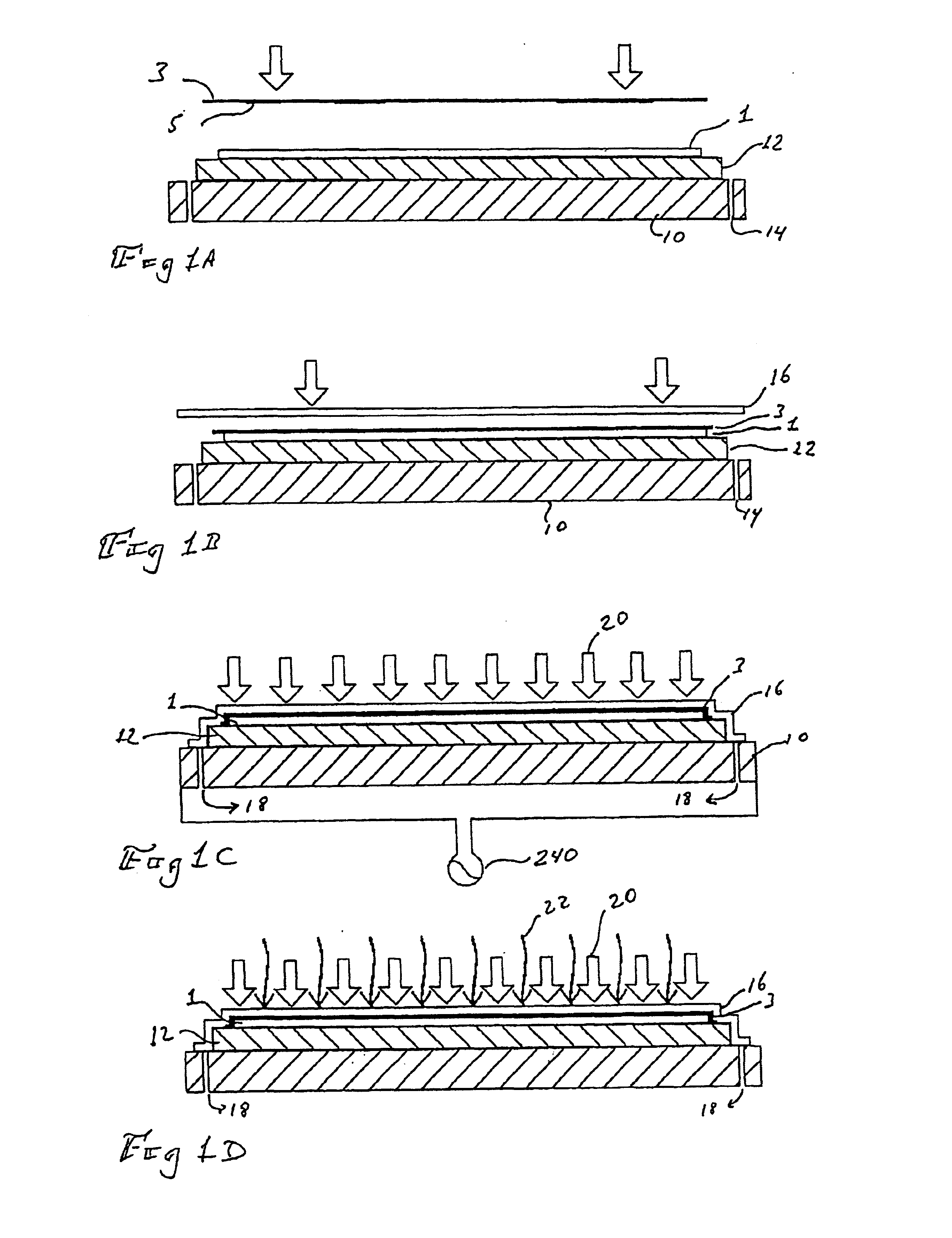
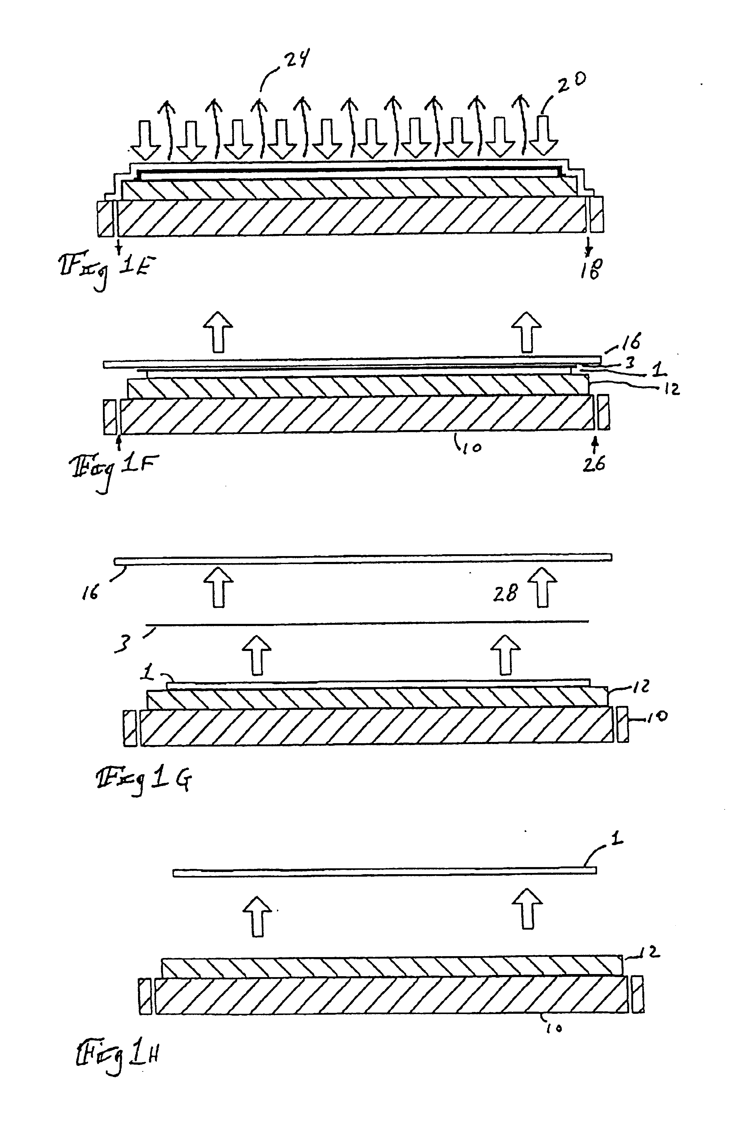
[0049]Having reference now to FIGS. 1A through 1H, a methodology taught by the present invention for forming dye sublimation images in substrates, particularly in solid plastic substrates, is shown. At FIG. 1A is shown a platen, 10, having superimposed thereon a passive cooling device, 12. The principles of the present invention specifically contemplate the utilization of either or both active and passive cooling devices, as will be explained later. Platen 10, in one embodiment of the present invention, is...


PUM

PropertyMeasurementUnit
pressureaaaaaaaaaa
temperatureaaaaaaaaaa
pressureaaaaaaaaaa

Abstract

Method for forming a dye sublimation image in a substrate, particularly a plastic substrate, and apparatus to perform the method. According to the method taught by the present invention, a substrate is disposed on a perforated platen and a dye carrier having an image formed thereon of a dye sublimation ink is disposed on the substrate such that the image is in contact with the substrate. The substrate, dye carrier and at least a portion of the perforated platen are then covered with a flexible membrane. A clamping pressure is then applied to the substrate and the dye carrier through the membrane. Once the clamping pressure is attained, the substrate and dye carrier are first heated, then cooled.The invention disclosed herein further teaches a number of novel apparatus to effect the method, resulting in significantly superior dye sublimation imaging than heretofore attainable in rigid plastic sheets.

Description

FIELD OF THE INVENTION[0001]The present invention relates to the formation of images within solid sheets of plastic. More particularly, the present invention relates to a methodology for forming dye sublimation, or dye transfer, images within solid sheets of plastic and to an apparatus for performing the methodology.BACKGROUND OF THE INVENTION[0002]From the advent of plastics, users and manufacturers thereof have sought a workable means for imprinting or forming images thereon. Prior imaging technologies suitable for use on other materials, for instance metals, wood, and the like, have not generally met with success when used to perform permanent imaging plastics. Examples of such prior imaging technologies include but are not limited to paints, decals, lacquers, and dyes. In general the problems associated with utilizing prior imaging or marking technologies center on certain chemical and physical properties of plastics in general.[0003]One of the great advantages of plastics is th...

Claims


Application Information

Patent Timeline
Patent Type & Authority Patents(United States)
IPC IPC(8): B44C1/165B44C1/00B29C45/14B41M5/025B41M5/035B44C1/17D06P5/28
CPCB41M5/0256B44C1/1712D06P5/004B29C45/14688B29C2045/14737Y10S428/914B41M5/035
Inventor MAGEE, TED N.DRAKE, JONATHAN C.ESSERT, RICKSHAW, ROBERT W.
Owner SEKISUI KYDEX LLC
Why Eureka
Try Eureka