
Extrusion method for three dimensional modeling

a three-dimensional modeling and extrusion technology, applied in the direction of additive manufacturing processes, manufacturing tools, coatings, etc., can solve the problems of reducing throughput and reliability, introducing significant alignment and calibration issues, and object corners are particularly problematic, so as to avoid smearing, reduce calibration requirements, cost and throughput problems, and ensure the effect of quality

Inactive Publication Date: 2006-02-14
STRATSYS INC
View PDF16 Cites 139 Cited by
  • Summary
  • Abstract
  • Description
  • Claims
  • Application Information

AI Technical Summary

Benefits of technology

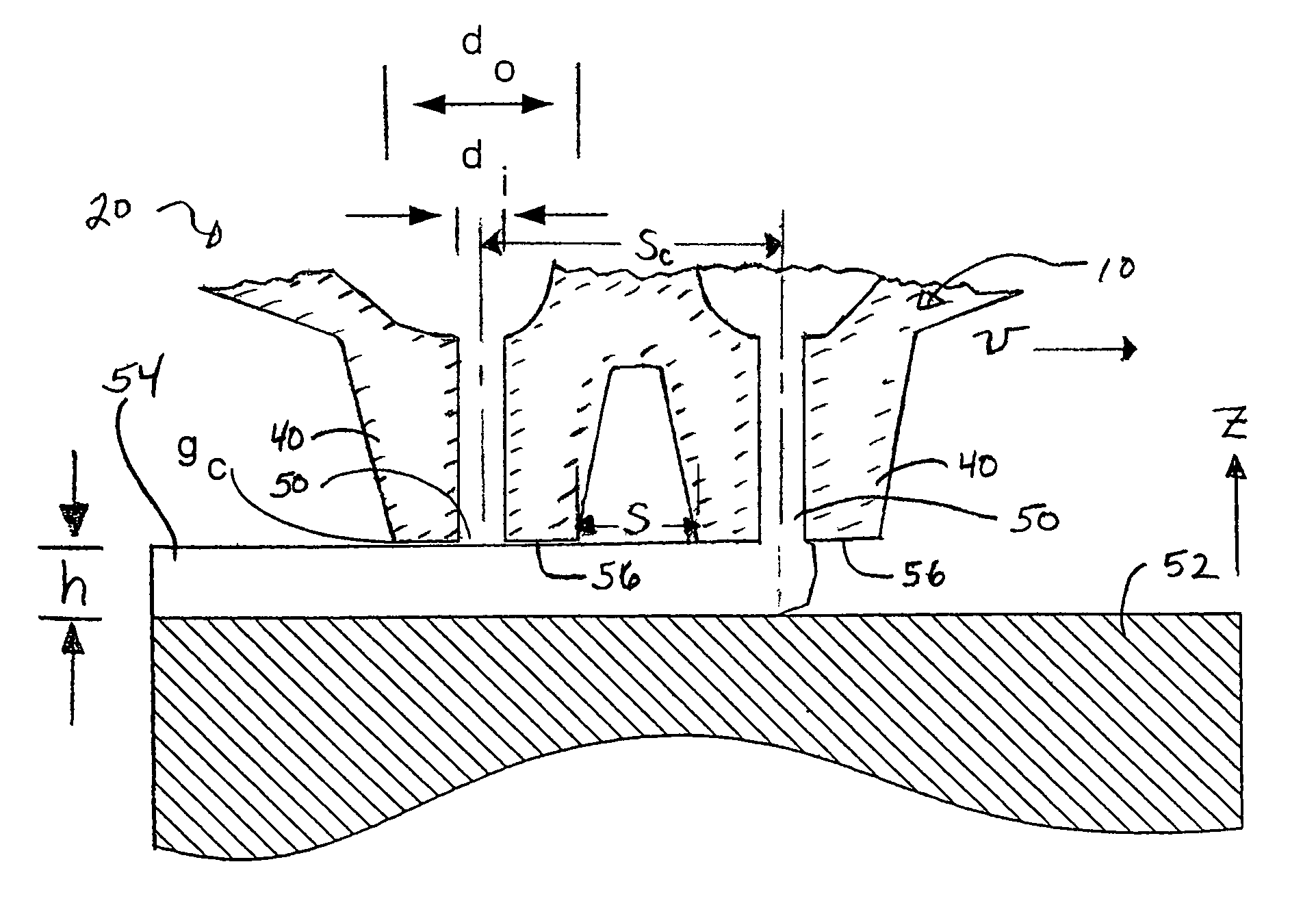
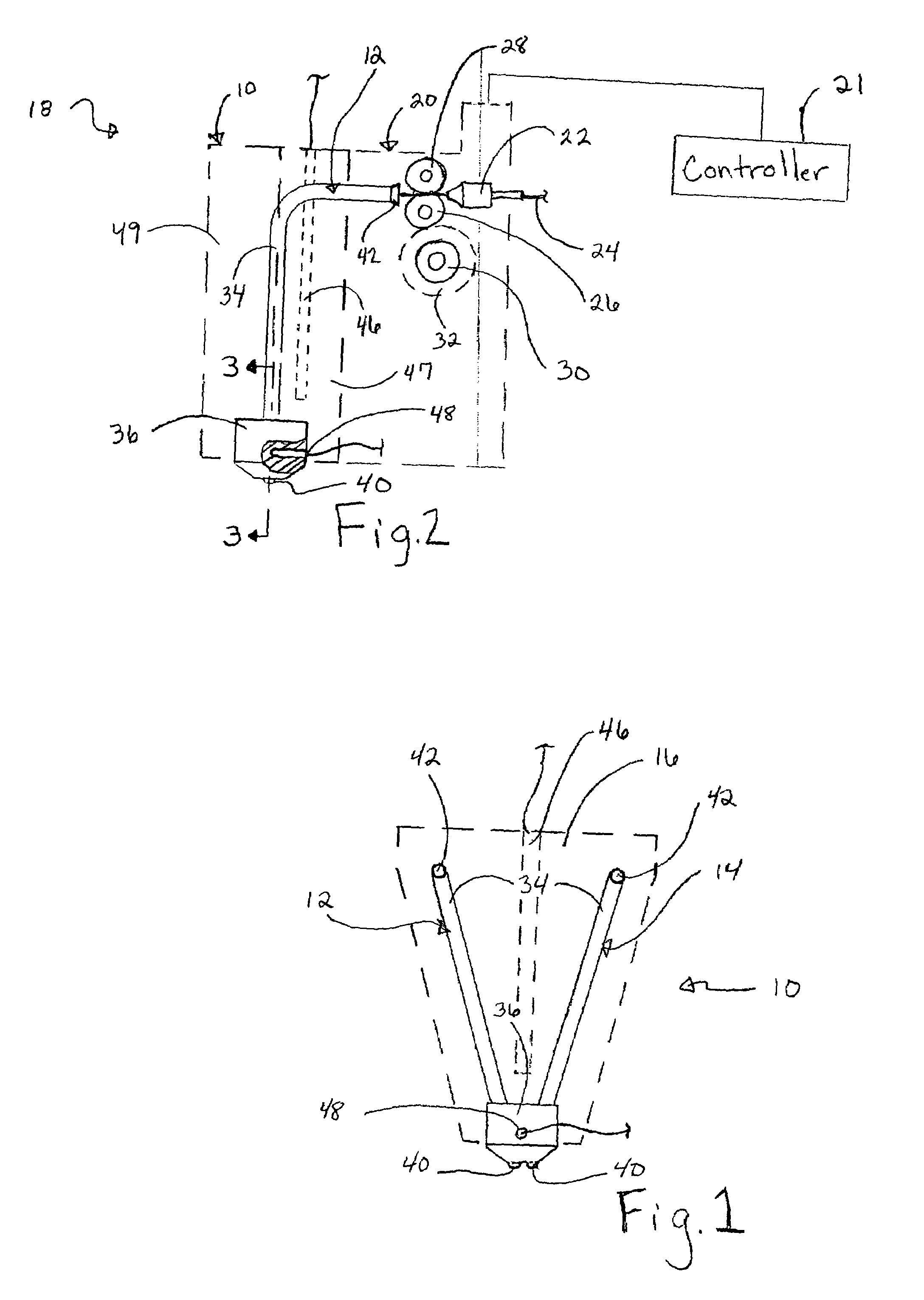
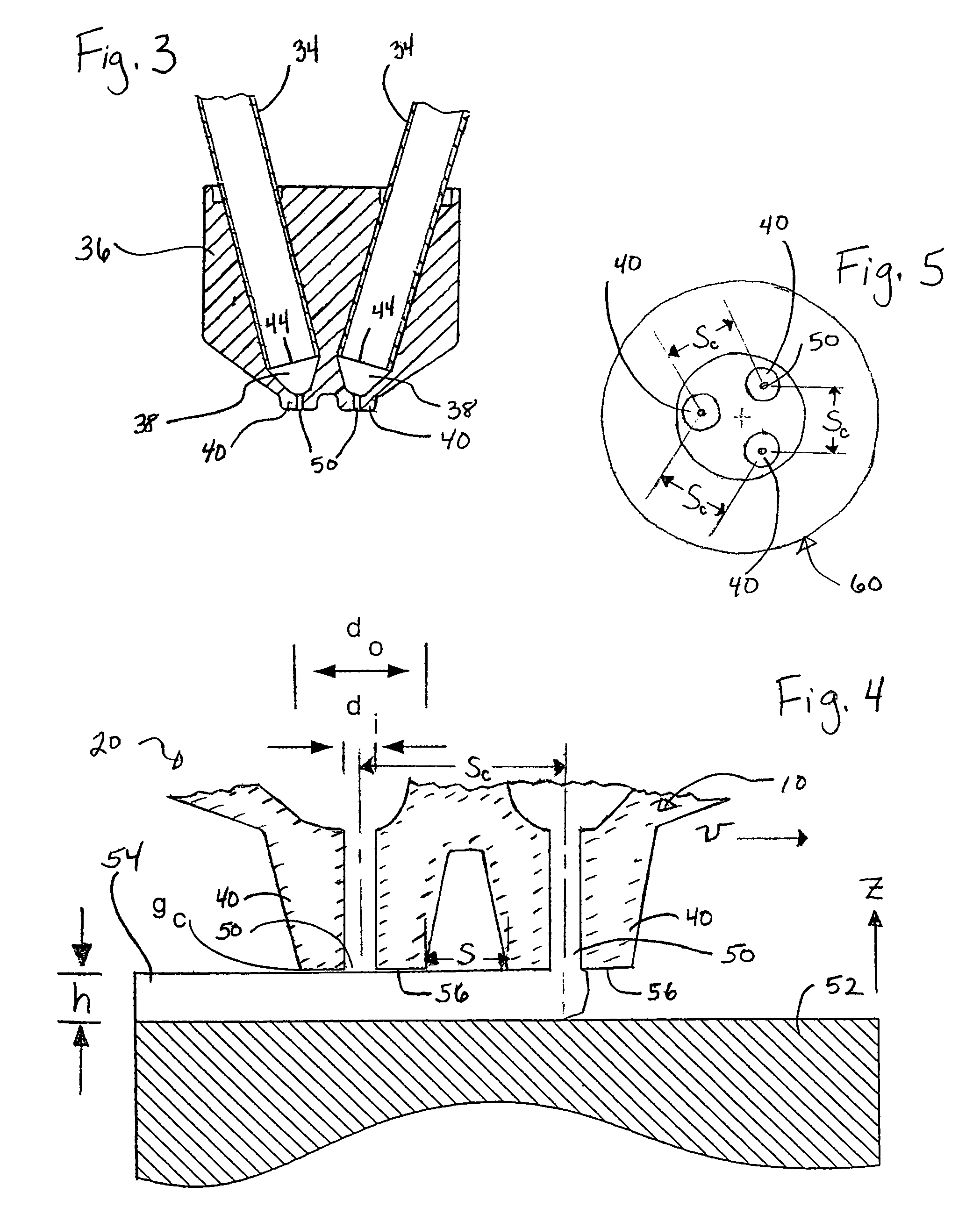
[0013]The present invention is a multi-tip extrusion method for building a three-dimensional object, whereby modeling materials from distinct supply sources are each deposited in a layerwise predetermined pattern from dispensers having co-planar dispensing tips. The tip spacing is controlled so that a road of material extruded by a leading one of the tips will cool and shrink from the plane of the tips before a trailing one of the tips passes over the extruded road. The trailing tip therefore does not smear the road. A minimum transit time between tips can be calculated as a function of road height and thermal diffusivity of the material forming the road. The method of the present invention avoids the smearing, calibration, reliability, cost and throughput issues of the prior art techniques, enabling efficient production of good quality models. Z.

Problems solved by technology

Object corners are particularly problematic.
While the apparatus of the '785 patent eliminates smearing problems, it introduces significant issues of alignment and calibration.
Calibration requirements decrease throughput and reliability.
The mechanical complexity of toggling the two tips additionally lowers reliability and increases cost of the machine.
These methods have disadvantages as well.
Where two extrusion heads are provided, cost and size of the modeling machine are increased.
Additionally, tip calibration becomes more difficult.
A single tip dispensing two different materials avoids calibration issues but introduces other problems.
Material as well as build time are wasted in purging the tip.
Also, if any of a first material remains despite the purging effort, the remaining first material will contaminate the second material resulting in possible degradation of model quality.
None of the known methods for dispensing multiple materials from different material supply sources are entirely satisfactory.

Method used


Image

  • Extrusion method for three dimensional modeling
  • Extrusion method for three dimensional modeling
  • Extrusion method for three dimensional modeling

Examples


example

[0057]An example is given in which theoretical results are compared to experimental results. In this example, the build conditions are that of a Stratasys FDM® three-dimensional modeling machine depositing ABS thermoplastic, according to the parameters given in Table 1 below:

[0058]

TABLE 1VARIABLEVALUEdo45 mils (1.14E-4 meter)di12 mils (3.05E-4 meter)Sc100 mils (2.54E-3 meter)h10 mils (2.54E-4 meter)νmin0.9 ips (0.023 meter / sec)αmax3 inches / sec2 (7.77E-3 g's)ke1.4 watt / (meter ° C.)Cp1.8 joule / (gram ° C.)Te270° C.Tg140° C.Th70° C.α8E-5 / ° C.ρ1.1 gram / centimeter3ka0.016 watt / (meter ° C.)

The thermal diffusivity for the above example parameters, calculated according to equation (1), is 7.07E-7 meters2 / sec. The critical gap, calculated according to equation (2), is 0.06 mils (1.5 microns). Applying equation (3), the change in temperature required to create the critical gap is predicted to be 72° C. The time required to create this change in temperature, predicted according to equation (4),...


PUM

PropertyMeasurementUnit
Heightaaaaaaaaaa
Velocityaaaaaaaaaa
Thermal diffusivityaaaaaaaaaa

Abstract

A multi-tip extrusion method and apparatus for building a three-dimensional object deposits modeling materials from distinct supply sources, each in a layerwise predetermined pattern, from dispensers having co-planar dispensing tips. The tip spacing is controlled so that a road of material extruded by a leading one of the tips will cool and shrink from the plane of the tips before a trailing one of the tips passes over the road. In this manner, smearing of the road by a trailing one of the tips is avoided.

Description

CROSS-REFERENCE TO RELATED APPLICATION(S)[0001]This application is a divisional of application Ser. No. 09 / 845,566, filed Apr. 30, 2001, now U.S. Pat. No. 6,749,414 which is hereby incorporated by reference as if set forth fully herein.BACKGROUND OF THE INVENTION[0002]This invention relates to the fabrication of three-dimensional objects using extrusion-based layered manufacturing techniques. More particularly, the invention relates to forming three-dimensional objects from multiple types of modeling materials that are extruded in a flowable state and solidify after being deposited onto a base.[0003]Three-dimensional models are used for functions including aesthetic judgments, proofing the mathematical CAD model, forming hard tooling, studying interference and space allocation, and testing functionality. Extrusion-based layered manufacturing machines build up three-dimensional models by extruding solidifiable modeling material from a nozzle tip carried by an extrusion head onto a ba...

Claims


Application Information

Patent Timeline
IPC IPC(8): B29C41/02B29C48/05B29C48/345B29C67/00
CPCB29C47/0007B29C67/0055B29C47/30B29C47/86B29C47/0009B29C47/0014B29C48/865B29C48/05B29C48/023B29C48/03B29C48/345B29C48/86B33Y30/00B29C64/118B29C64/106B33Y50/02
Inventor HANSON, JEFFERY J.BOSVELD, MICHAEL DAVIDBATCHELDER, JOHN SAMUEL
Owner STRATSYS INC
Learn More