Power factor correction circuit for electronic ballast

a technology of electronic ballast and power factor, which is applied in the direction of electrical equipment, instruments, light sources, etc., can solve the problems of reducing power factor, increasing harmonics, increasing electromagnetic interference, etc., and achieves less harmonics, increased rc time constant, and smoke waveform

Inactive Publication Date: 2006-02-14
CHIOU YIH FANG
View PDF4 Cites 12 Cited by
  • Summary
  • Abstract
  • Description
  • Claims
  • Application Information

AI Technical Summary

Benefits of technology

[0008]The present invention provides a power factor correction circuit, which comprises a plurality of diodes and capacitors and is located between a bridge rectifier circuit and a high frequency oscillation circuit to replace a single-capacitor DC filter circuit of the conventional electronic ballast. The power factor correction circuit according to the present invention comprises a filtering capacitor charge / discharge circuit and a feedback circuit taking input from a lamp filament. The former offers a smaller equivalent filtering capacitance so that the input AC current has a smoother waveform and thereby a less amount of harmonics is achieved. The former also offers a larger equivalent capacitance so that the RC time constant is increased when discharging to the load. This in turn reduces the ripple fluctuation and therefore the crest factor of the lamp current. On the other hand, the latter further adds the high frequency voltage feedback from the lamp filament onto the low frequency DC voltage output from the bridge rectifier circuit so that the waveform of the input AC current can further approach true sine wave.
[0009]The power factor correction circuit provided by the present invention achieves simultaneously a low amount of input AC current harmonics (the total harmonic distortion <10%), a high power factor (the power factor >0.95), and a less-than-rating lamp current crest factor (the lamp current crest factor <1.7). The provided power factor correction circuit also has advantages, such as small form factor, low cost, and high working reliability. The power factor correction circuit according to the present invention is especially suitable for application in self-excited electronic ballasts with small to medium power consumption.

Problems solved by technology

The increase of harmonics intensifies electromagnetic interference.
If a large number of such electronic ballasts are used simultaneously, there is a high possibility to cause a tripping of the power supply system or even a fire accident in the worst case.
On the other hand, a reduction of power factor would increase the power consumption of the power supply system and therefore the power bill as well.
In other words, these so-called “high efficient” electronic ballasts actually have a high amount of harmonics and a rather low power factor.
The active power factor correction circuits adopt active elements and therefore have a complex structure, bulky form factor, and a higher cost.
The passive power factor correction circuits can only achieve limited improvement and therefore have little value in real-life applications.

Method used


Image

  • Power factor correction circuit for electronic ballast
  • Power factor correction circuit for electronic ballast
  • Power factor correction circuit for electronic ballast

Examples


Embodiment Construction

[0015]A power factor correction circuit provided by the present invention is structured on and works along with a conventional electronic ballast circuit. A preferred embodiment of the power factor correction circuit in accordance with the present invention is described in details as follows.

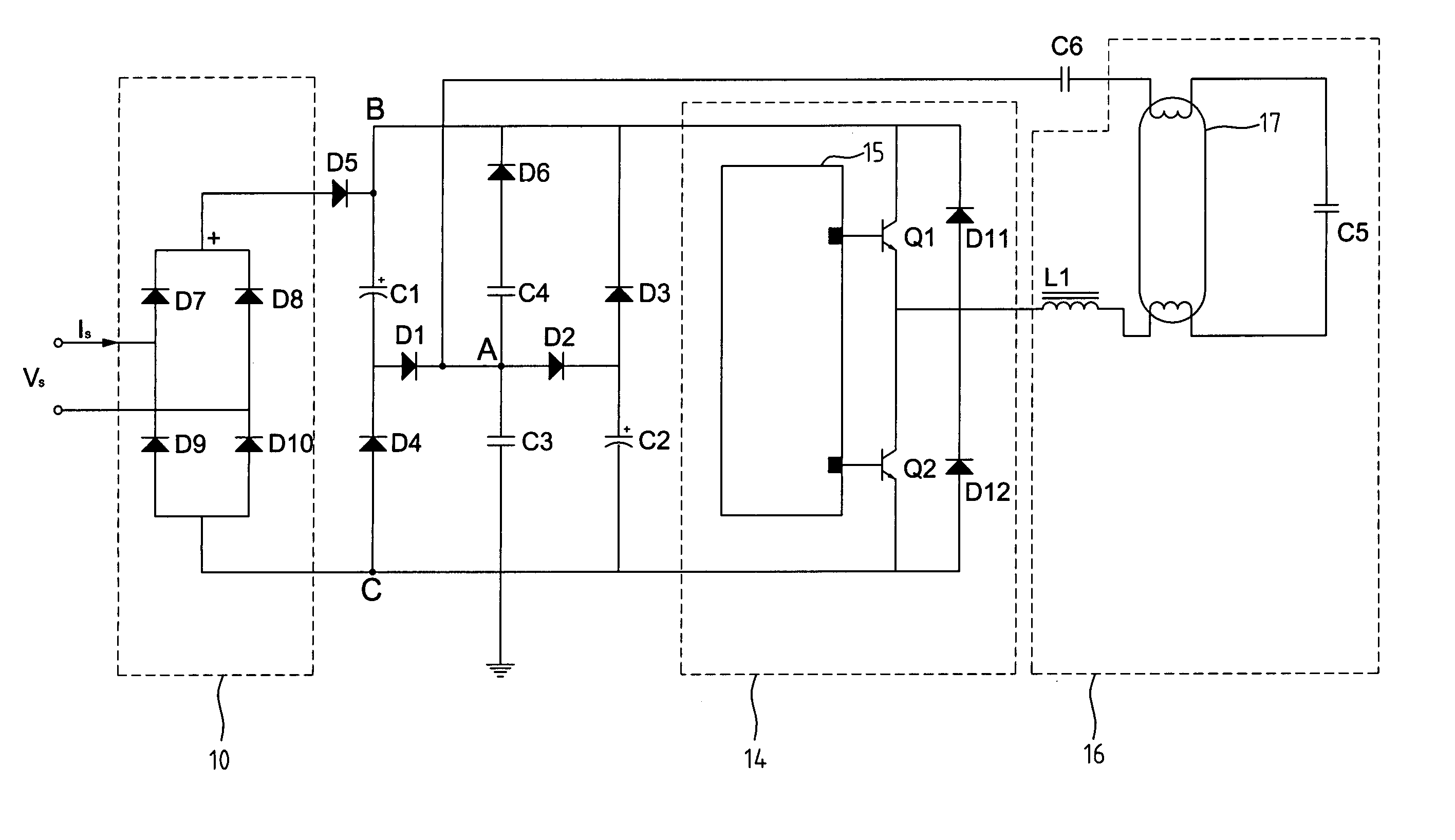
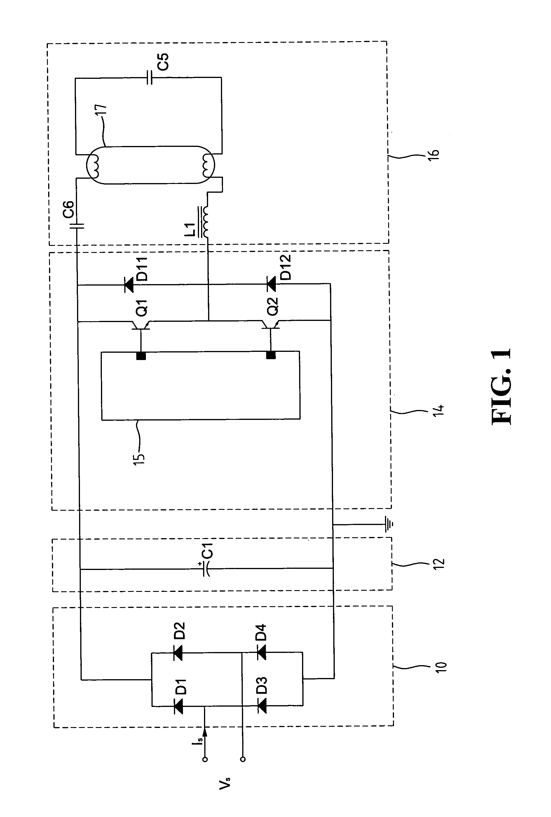
[0016]FIG. 3 is a circuit diagram of the electronic ballast according to the preferred embodiment of the present invention. As shown in FIG. 3, a bridge rectifier circuit 10, a high frequency oscillation circuit 14, and a lamp circuit 16 of the electronic ballast of the present invention are generally identical to the counterparts employed in a conventional electronic ballast and thus, some details may be neglected for simplifying the present description.

[0017]The power factor correction circuit provided by the present invention comprises a filtering capacitor charge / discharge circuit and a feedback circuit. Details about the filtering capacitor charge / discharge circuit are explained first as fo...


PUM


Abstract

A power factor correction circuit for the electronic ballast of a fluorescent lamp is provided. The power factor correction circuit is located between a bridge rectifier circuit and A high frequency oscillation circuit of the electronic ballast, and includes a filtering capacitor charge / discharge circuit and a feedback circuit taking input from a filament of the fluorescent lamp. The electronic ballast equipped with the power factor correction circuit achieves a power factor >0.95, a lamp current crest factor <1.7, and a total harmonic distortion <10%.

Description

FIELD OF THE INVENTION[0001]The present invention generally relates to electronic ballast of fluorescent lamps, and more specifically to a power factor correction circuit for the electronic ballast of the fluorescent lamp.BACKGROUND OF THE INVENTION[0002]Electronic ballasts, due to its small form factor, light weight, less power consumption, and stable light beams, have become the mainstream of fluorescent lamp ballast. Basically the electronic ballast is a combination of circuits that converts alternating current (AC) into direct current (DC) and then from DC back to AC. More specifically, one of the conventional electronic ballasts converts the AC voltage from the mains into a DC voltage, and then converts the DC voltage, through high frequency oscillation, into a high frequency, high level AC voltage to excite the fluorescent lamp. As shown in FIG. 1, the conventional electronic ballast contains a bridge rectifier circuit 10, a DC filter circuit 12, a high frequency oscillation c...

Claims


Application Information

Patent Timeline
Patent Type & Authority Patents(United States)
IPC IPC(8): H05B41/16H05B39/04H05B41/28H05B41/282H05B41/36
CPCH05B41/28H05B41/282Y10S315/05
Inventor CHIOU, YIH-FANG
Owner CHIOU YIH FANG
Why Eureka
Try Eureka