Three-dimensional image display system

a display system and three-dimensional technology, applied in optics, instruments, electrical equipment, etc., can solve the problems of unnaturalness, large cost of full color holography on a large screen, many drawbacks of integral photography, etc., to prevent the generation of crosstalk images, wide visual angle, and invasion of adjacent images

Inactive Publication Date: 2006-02-14
KOBAYASHI TETSURO
View PDF9 Cites 37 Cited by
  • Summary
  • Abstract
  • Description
  • Claims
  • Application Information

AI Technical Summary

Benefits of technology

[0038][10] A three-dimensional image display system including a transparent medium with a refractive index of more than one disposed between a image panel or a color filter and a parallax barrier, a slit,

Problems solved by technology

As described thus far, full color holography for large screen involves considerably high cost; therefore, holography is not used for real-time display of 3D images and stereoscopic movies, although holography is presently used for mediums for recording digital data, as well as for credit cards and ornaments, in which holography can be implemented in a small scale.
Therefore, the focus position does not coi

Method used


Image

  • Three-dimensional image display system
  • Three-dimensional image display system
  • Three-dimensional image display system

Examples


first embodiment

[0062]the invention will now be described.

[0063]A parallax system in which glasses are not used and a barrier is used will be described since it is necessary for understanding the invention.

[0064]FIG. 6 shows a basic principle of a binocular parallax type parallax stereogram, which is the simplest in the systems utilizing parallax.

[0065]In this figure, reference numeral 1 designates a screen or a panel on which images are drawn; 2 designates a barrier having slits 2a; 3 designates an observer (3a designates a right eye, 3b designates a left eye); 4 designates an image for the right eye; and 5 designates an image for the left eye.

[0066]On the screen or the panel 1, vertically sliced images taking parallax for the left eye and for the right eye into account are drawn alternately, and a barrier 2 having slits 2a formed in such a manner that the right eye 3a can only see the image 4 for the right eye and the image 5 for the left eye is blocked, and vice versa, is disposed on the observe...

second embodiment

[0095 of the invention will now be described.

[0096]FIG. 15 is a drawing showing a basic structure of the wide visual angle three-dimensional image display system in which crosstalk images are prevented from being generated according to the invention.

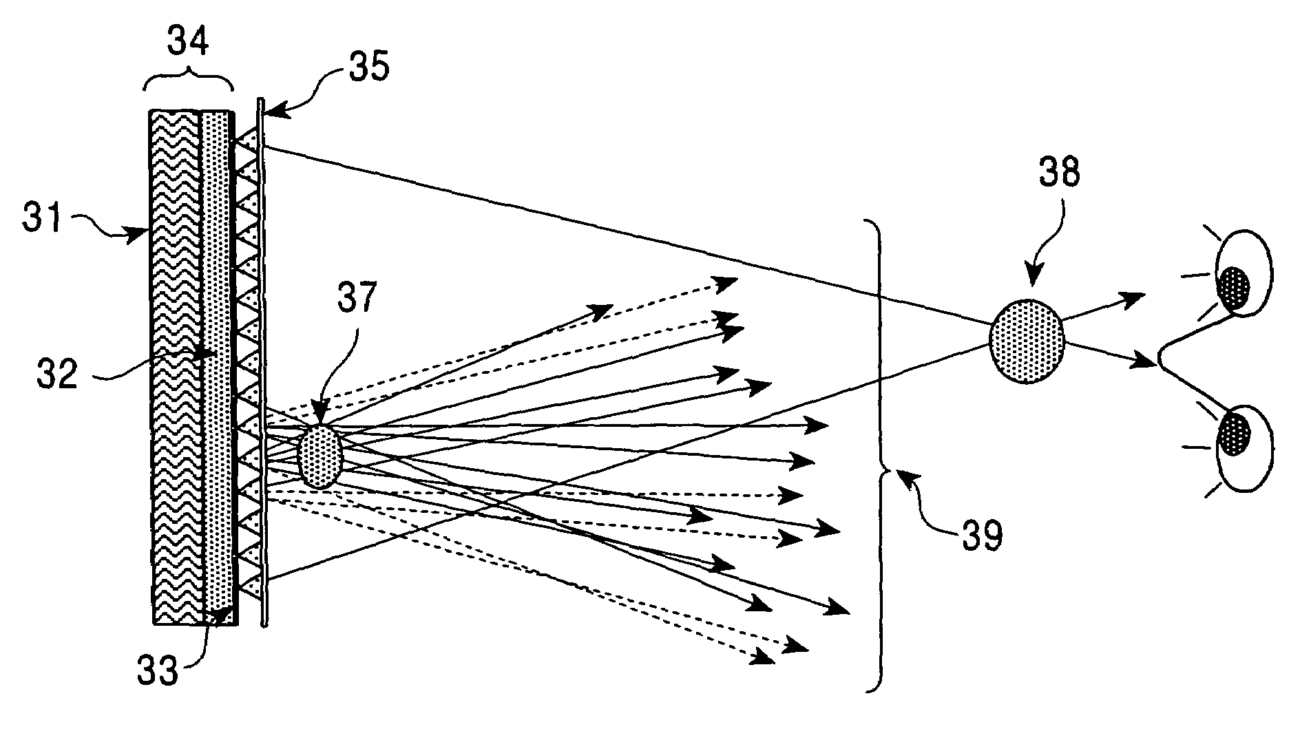
[0097]In this figure, reference numeral 101 designates a display unit; 102 designates a white-color point light source array; 103 designates a transparent medium having a refractive index of more than one; 104 designates a color filter (that may be a liquid crystal); 105 designates a observer; 106 designates a reproduced 3D image; 107 designates a white-color light emitted from the white-color point light source array 102; and 108 designates refraction of the light beam 107.

[0098]As shown in FIG. 15, the portion of the light beams 107 emitted from the white-color point light source array 102 is adequately weighed and colored by the color filter 104 and converted into a light beam forming 3D images.

[0099]Reproduction of the image in the v...


PUM


Abstract

A three-dimensional image display system utilizing both a light beam reproducing method and a shadowgraph multi-view parallax method, including a color filter is disposed on an observer side of a white-color point light source array, and, in an area apart from the color filter and white point light source, light beams emitted from the white-color point light source are selectively colored by the color filter for generating an image of each point of an object, while in the region in the vicinity of the point light source and the color filter, the light beams are selectively colored by the color filter so that image data reaching the eye from the white-color point light source through the color filter performs a view-dependent parallax stereoscopic display operation not only laterally but also vertically, and in the intermediate region, these two operations are mixed, so that a stereoscopic image is continuously formed.

Description

TECHNICAL FIELD[0001]The present invention relates to a wide visual angle three-dimensional image display system utilizing both a light beam reproducing method and a shadowgraph type multi-view parallax method while preventing crosstalk images from being generated.BACKGROUND ART[0002]Conventional techniques for recording and reproducing stereoscopic images include holography utilizing light coherence and a method that utilizes a plurality of images but not coherence. The latter is generally classified into two schemes; i.e., a binocular parallax type stereoscope scheme in which a two-dimensional image for the right eye and a two-dimensional image for the left eye are recorded, and the recorded images are reproduced such that an observer can see the image for the right eye through his right eye and the image for the left eye through his left eye; and a multi-view parallax type scheme utilizing images viewed from multiple points of view.[0003]In holography, which is an ideal method of...

Claims


Application Information

Patent Timeline
IPC IPC(8): H04N13/04G02B27/48G02B30/30H04N13/00H04N15/00
CPCG02B27/2214G02B27/48H04N13/0422H04N13/0409H04N13/0418H04N13/0404H04N13/305H04N13/32H04N13/324H04N13/31G02B30/30G02B30/27
Inventor KOBAYASHI, TETSURO
Owner KOBAYASHI TETSURO
Why Eureka
Try Eureka