Optical systems with diversity detection

a technology of optical systems and diversity, applied in the field of communication, can solve the problems of reducing the dispersion effect of optical systems that utilize these transmission technologies, affecting the reliability of optical systems, so as to achieve greater reliability and reduce the dispersion

Active Publication Date: 2006-02-14
T MOBILE INNOVATIONS LLC
View PDF4 Cites 21 Cited by
  • Summary
  • Abstract
  • Description
  • Claims
  • Application Information

AI Technical Summary

Benefits of technology

[0017]The receiver system advantageously reduces dispersion effects such as polarization mode dispersion by applying radio frequency detection. The radio frequency detection is advantageous over the optical delay line and RF delay line based on the absence of mechanical parts, which thus provides greater reliability. The detection system can then use electrical circuits to apply radio frequency detection, which is small in size, reliable, and integratable.

Problems solved by technology

Commercial WDM systems are limited by channel spacing of about 50 GHz due to selectivity of optical filters and limitations in the wavelength stability of semiconductor lasers.
Optical system that utilize these transmission technologies experience signal degradation such as non-linear crosstalk, chromatic dispersion, and polarization mode dispersion (PMD) especially with higher data rates and long distance transmissions.
Thus, compensating for PMD can be difficult because of the time varying nature and randomness of PMD.
One problem with the PMD compensation system 100 is the optical delay line 112.
One limitation of this tunable optical delay line with a motorized machine is the speed of tuning, which is inversely proportional to the tuning range.
The optical delay line is slow and also bulky.
Another problem is the long term reliability of mechanical moving parts of the optical delay line, which perform continuous adjustment in an operational optical system.
Unfortunately, this prior solution also experiences the same problems of the optical delay line such as reliability with the RF delay line.
However, PMD-induced signal fading in SCM systems depends on the frequency of the sub-carrier, which is typically higher than the data rate.

Method used


Image

  • Optical systems with diversity detection
  • Optical systems with diversity detection
  • Optical systems with diversity detection

Examples


Embodiment Construction

Receiver System—FIGS. 2–3

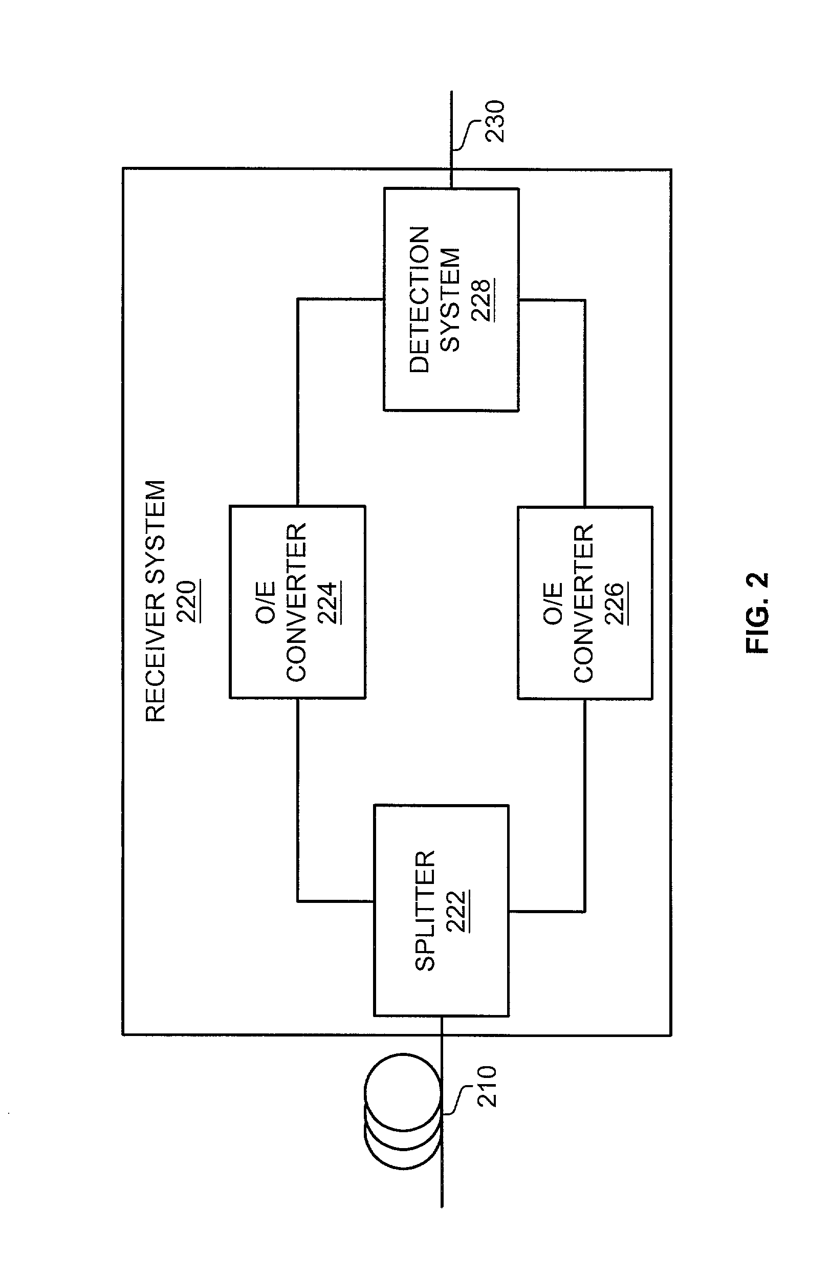
[0026]FIG. 2 depicts a block diagram of a receiver system 220 in an example of the invention. The receiver system 220 comprises a splitter 222, an optical to electrical (O / E) converter 224, an O / E converter 226, and a detection system 228. An optic fiber link 210 is connected to the splitter 222. The splitter 222 is connected to the O / E converter 224 and the O / E converter 226. The detection system 228 is connected to the O / E converter 224, the O / E converter 226, and an output link 230.

[0027]The splitter 222 is any system or device configured to split a received optical signal based on polarization into a first optical signal and a second optical signal. One example of the splitter 222 is a polarization beam splitter. The O / E converter 224 and the O / E converter 226 are any system or device configured to convert an optical signal into an electrical signal. Some examples of the O / E converter 224 and the O / E converter 226 are photodiodes. The detection system 22...


PUM


Abstract

A receiver system processes a received optical signal that carries user information. The receiver system includes a splitter, a first converter, a second converter, and a detection system. The splitter splits the received optical signal based on polarization into a first optical signal and a second optical signal. The first converter converts the first optical signal into a corresponding first electrical signal. The second converter also converts the second optical signal into a corresponding second electrical signal. The detection system applies radio frequency detection to the first electrical signal to generate a third electrical signal. The detection system applies radio frequency detection to the second electrical signal to generate a fourth electrical signal. The detection system then combines the third electrical signal and the fourth electrical signal to form a fifth electrical signal that carries the user information.

Description

RELATED APPLICATIONS[0001]Not applicableFEDERALLY SPONSORED RESEARCH OR DEVELOPMENT[0002]Not applicableMICROFICHE APPENDIX[0003]Not applicableBACKGROUND OF THE INVENTION[0004]1. Field of the Invention[0005]The invention is related to the field of communications, and in particular, to a communication system for processing received optical signals that carry user information.[0006]2. Description of the Prior Art[0007]Transmission technologies such as multiplexing are used to increase the bandwidth provided by optical fibers. One transmission technology called time division multiplexing (TDM) interleaves multiple channels or signals into one optical signal. Another transmission technology called wavelength division multiplexing (WDM) transmits multiple signals at different wavelengths, where low data rates are used on each wavelength. Commercial WDM systems are limited by channel spacing of about 50 GHz due to selectivity of optical filters and limitations in the wavelength stability o...

Claims


Application Information

Patent Timeline
Patent Type & Authority Patents(United States)
IPC IPC(8): H04B10/06
CPCH04B10/66H04B10/032
Inventor HUI, RONGQINGALLEN, CHRISTOPHER T.DEMAREST, KENNETH ROBERT
Owner T MOBILE INNOVATIONS LLC
Why Eureka
Try Eureka