

Decoding system and method in an optical disk storage device
a decoding system and optical disk technology, applied in the direction of coding, digital signal error detection/correction, recording signal processing, etc., can solve the problems of limiting the speed of the entire dvd system for many accesses to the data buffer, taking a lot of time, etc., to increase the decoding speed, enhance the parallel processing capability of the decoding system, and reduce the access time to the data buffer
- Summary
- Abstract
- Description
- Claims
- Application Information
AI Technical Summary
Benefits of technology
Problems solved by technology
Method used
Image

Examples
first embodiment
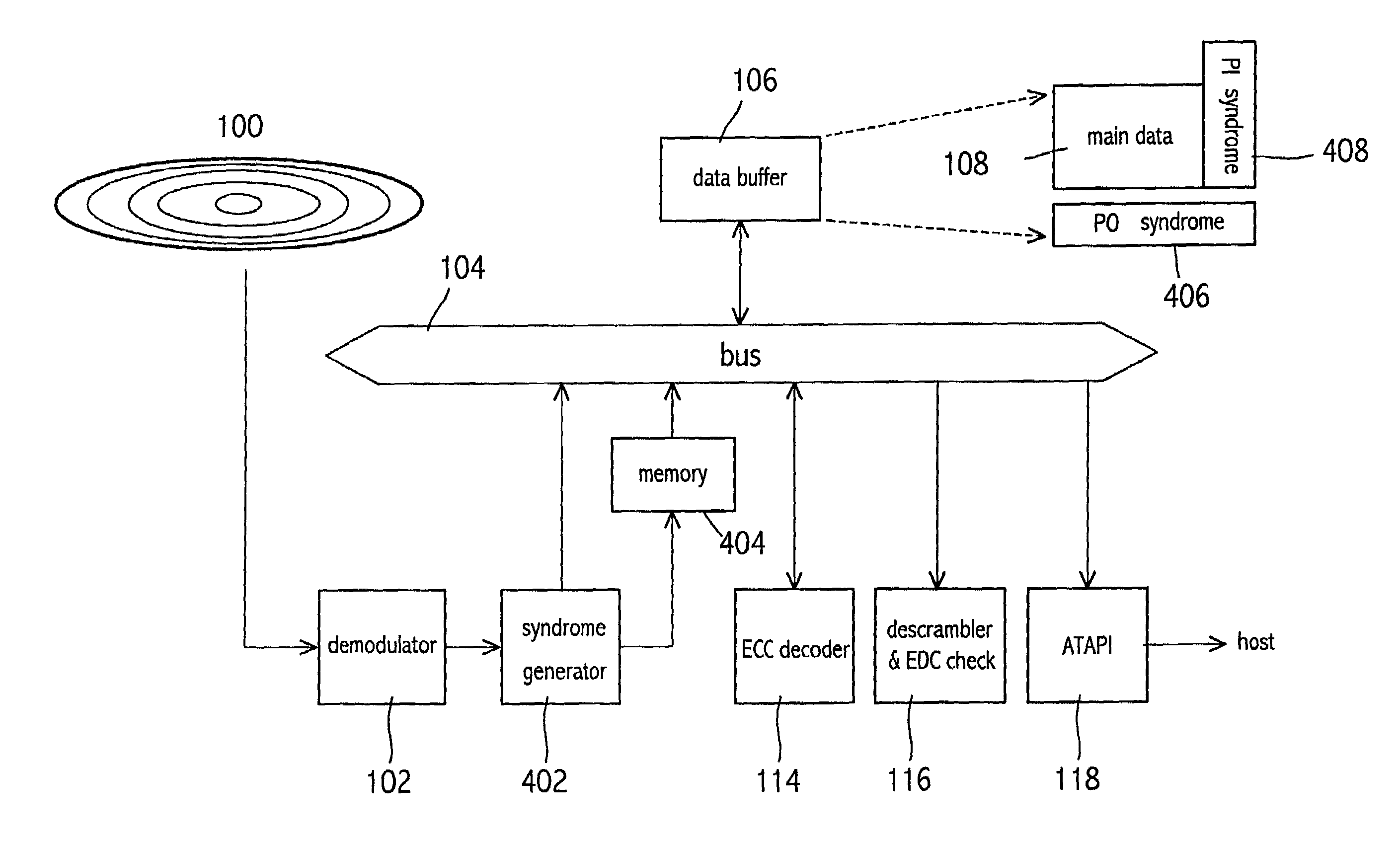
[0028]Turning now to FIG. 4, it illustrates a block diagram of the present invention. The decoding system in FIG. 4 is similar to FIG. 1. The difference is that the data stored in the data buffer 106 are main data 108, PO syndrome 406, and the PI syndrome 408, wherein the scale of the main data 108 is 192*172 bytes, the scale of the PO syndrome 406 is 208*10 bytes, and the scale of the PI syndrome 408 is 16*182 bytes. Besides, the demodulator 102 transfers directly the ECC block to a syndrome generator 402 after finishing the demodulation process. The syndrome generator 402 writes the main data 108 into the data buffer 106 and calculates the PI syndrome 408 and the PO syndrome 406 by using the PI and the PO of the ECC block. After the syndrome generation, the PI and the PO are abandoned. Since the demodulator 102 transfers the ECC block along the PI direction of the ECC block, the syndrome generator 402 generates and stores the PI syndrome 408 directly into the data buffer 106. Whil...
second embodiment
[0030]Referring now to FIG. 5, it illustrates a block diagram of the present invention. The structure of FIG. 5 is similar to FIG. 4, the difference is that the first data room 502 and the second data room 504 are connected to the ECC decoder 114. The ECC decoder 114 reads the PI syndrome 408 and the PO syndrome 406 from the data buffer 106 and writes the PI syndrome 408 and the PO syndrome 406 into the first data room 502 and the second data room 504 respectively to perform the error correction decoding, then writes the corrected PI syndrome 408, PO syndrome 406 into the first data room 502 and the second data room 504 respectively and writes the corrected part of the main data 108 into the data buffer 106. Afterward, the ECC decoder 114 only accesses to the first data room 502 and the second data room 504 to perform the ensuing error correction decoding. Therefore, the structure of FIG. 5 can reduce more access times to the data buffer 106 in comparison with FIG. 4.
third embodiment
[0031]Referring now to FIG. 6, it illustrates a block diagram of the present invention. The structure of FIG. 6 is similar to FIG. 4, the difference is that the syndrome generator 602 calculates only the PI syndrome 408, so the memory 404 of FIG. 4 is not needed. Besides, since the syndrome generator 602 does not calculate the PO syndrome, the data stored in the data buffer 106 are main data 108, the PO 110 and the PI syndrome 408, wherein the scale of the main data 108 is 192*172 bytes, the scale of the PO 110 is 16*172 bytes, and the scale of the PI syndrome 408 is 208*10 bytes.
[0032]Thus, regarding the access times to the data buffer 106 of FIG. 6, the syndrome generator 602 writes the main data 108, PO 110 and the PI syndrome 408 into the data buffer 106. The ECC decoder 114 only needs to read the PI syndrome 408 when performing the error correction decoding of the PI direction, and writes the corrected PI syndrome 408, PO 110 and the corrected part of the main data 108 into the...
PUM
 Abstract
Description
Claims
Application Information