Flexible thermally insulative and waterproof barrier

a technology of thermal insulation and waterproof barrier, applied in the direction of heat insulation, walls, transportation and packaging, etc., can solve the problems of weakening of the barrier in the joint area, structural problems, and breaking of the barrier in unsupported positions, and achieve the effect of being flexible enough

Inactive Publication Date: 2006-02-21
MEYER DONALD L
View PDF24 Cites 52 Cited by
  • Summary
  • Abstract
  • Description
  • Claims
  • Application Information

AI Technical Summary

Problems solved by technology

When butting the barrier pieces, the butting joints will be loose and, as a result, the barrier in the joint area is less effective.
The barrier cannot conform itself to the subsoil or the foundation, but only hits or rests on the high spots, thereby leaving voids under the barrier which can lead to breaking of the barrier in unsupported areas and possibly even structural problems with respect to concrete or other material poured thereover since the material is not installed to an even thickness.
On the other hand, overlapping of substantially inflexible barrier pieces creates an unattractive appearance, allows ambient winds to drive under a barrier piece to blow it out of position, and precludes the use of conventional flashing over the barrier.
Most importantly, overlapping barrier pieces may interfere with formation of an operatively continuous barrier as substantially inflexible barrier pieces will not substantially conform peripherally to a subsoil, foundation or wall, as necessary to provide an operatively continuous barrier.
Additionally, because of the voids caused by such overlapping of substantially inflexible barrier pieces at and adjacent the overlap, even the limited amount of walking on the barrier required for installation purposes may break the barrier pieces and thereby reduce the desired barrier properties.
As both butting joints and overlapping joints are not entirely satisfactory, the industry has for the most part used butting joints, but then sealed the butt joints, for example, with an adhesive sealing tape or like sealant.
In addition to the cost of the sealing tape or like sealant, substantial time and labor must be expended to operatively seal the butt joints, thereby increasing the effective cost of the barrier.
Additionally, in the known barrier materials, the thermal insulation within is not operatively sealed against exposure to moisture, which can deleteriously affect certain types of thermal insulation, such as aluminum.

Method used


Image

  • Flexible thermally insulative and waterproof barrier
  • Flexible thermally insulative and waterproof barrier
  • Flexible thermally insulative and waterproof barrier

Examples


Embodiment Construction

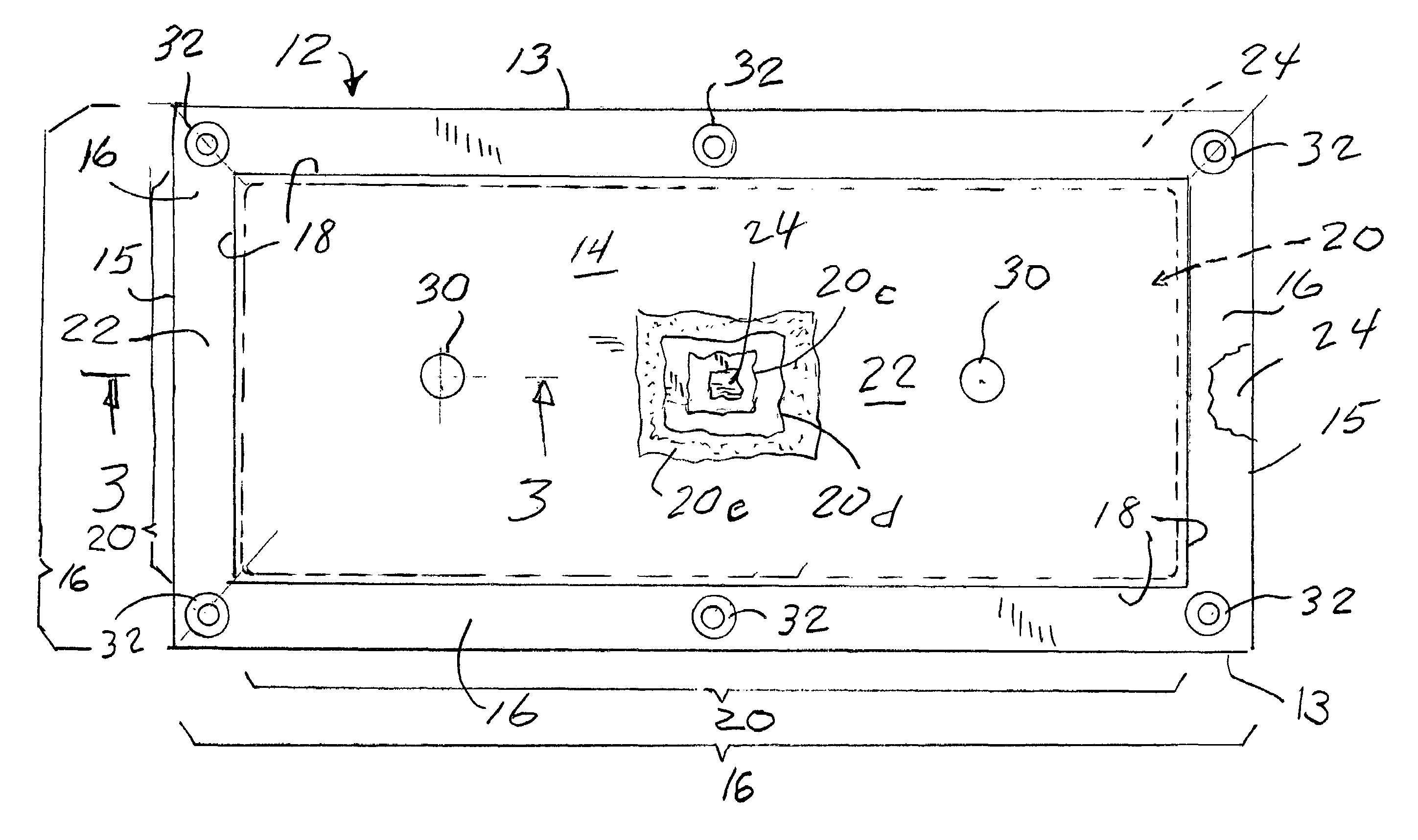
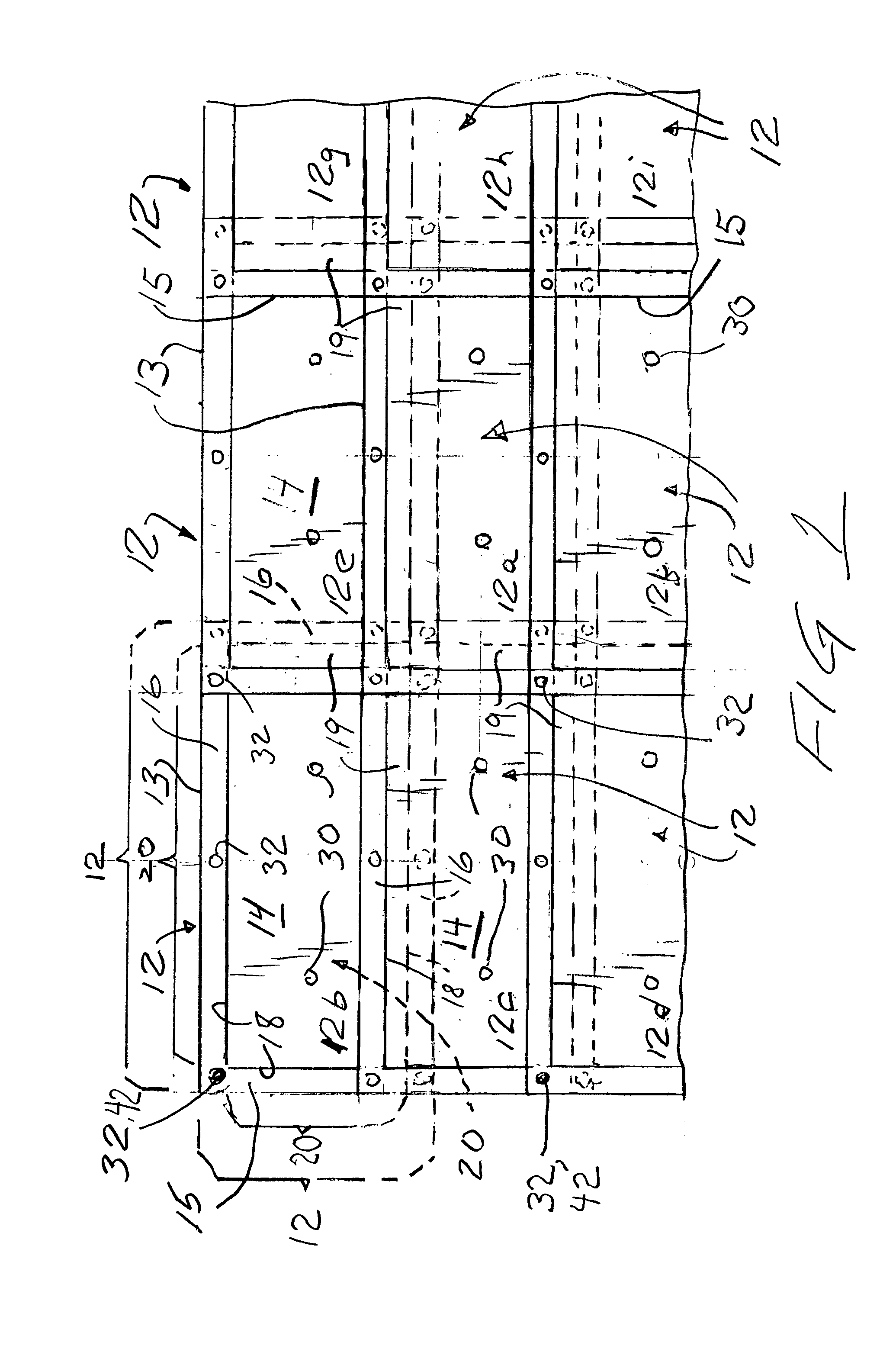
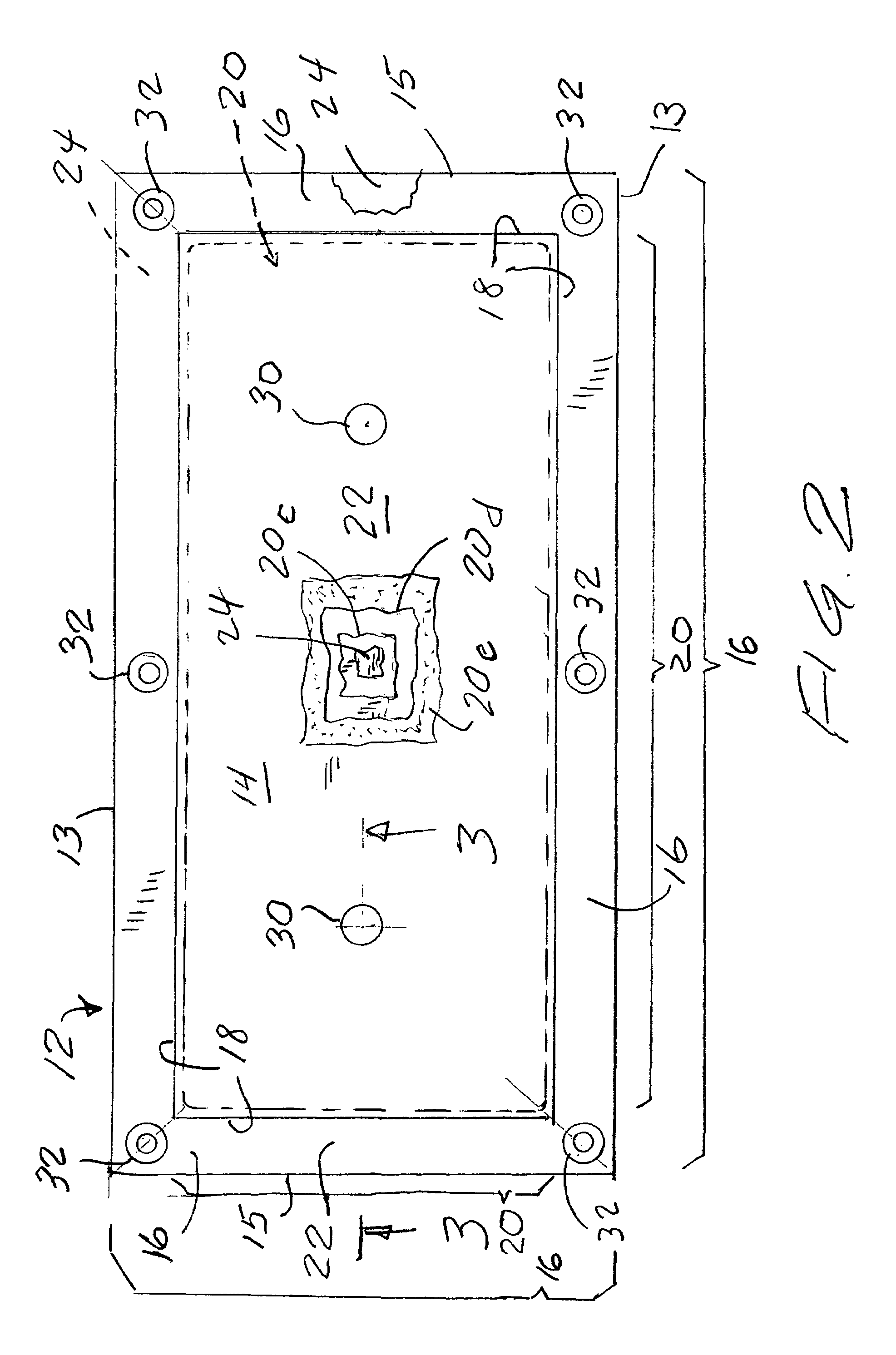
[0019]Referring now to the drawing, and in particular to FIG. 1 thereof, therein illustrated is a thermally insulative and waterproof barrier according to the present invention, generally designated by the reference numeral 10. The barrier 10 is intended for the protection of an exterior (not shown)—for example, a slab, foundation, wall or like structure, whether formed of concrete, brick or like construction material—against both heat (and loss of heat) and moisture. The term “exterior” is used herein and in the claims to broadly refer to any or all of the outer surfaces, including the sides, top and bottom.

[0020]The barrier 10 is comprised of a plurality of generally rectangular, substantially flexible blankets, generally designated 12, nine full blankets being illustrated in FIG. 1. Each blanket 12 defines a central body 14 having edges 18 and a peripheral margin 16 extending about the edges 18. The blankets 12 forming the barrier 10 are disposed relative to one another such that...


PUM


Abstract

A thermally insulative and waterproof barrier for protecting an exterior surface includes a plurality of generally rectangular flexible blankets in overlapping disposition. Each blanket defines a body and a peripheral margin about edges of the body, edges of the bodies of adjacent blankets (including the base layer) overlapping. Each body includes at least one base layer of thermal insulation and two cover layers of waterproof material. The cover layers are sealed together peripherally about the base layer to form the peripheral margin and exclude water from the base layer.

Description

BACKGROUND OF THE INVENTION[0001]The present invention relates to a thermally insulative and waterproof barrier for protecting an exterior surface and, more particularly, to such a barrier which is flexible.[0002]It is known in the construction art to provide a thermally insulative and waterproof barrier for protecting an exterior surface of a structure, whether the structure be a slab, a foundation, or a wall. Typically, the barrier is substantially inflexible so that the several pieces forming the barrier, when being installed, are placed both side-by-side and end-to-end to form butt joints. When butting the barrier pieces, the butting joints will be loose and, as a result, the barrier in the joint area is less effective. Thus, moisture and cold air can work its way into and through the joint, thereby reducing or eliminating the desired moisture and thermal barrier protection. The barrier cannot conform itself to the subsoil or the foundation, but only hits or rests on the high sp...

Claims


Application Information

Patent Timeline
Patent Type & Authority Patents(United States)
IPC IPC(8): E04C1/00E02D31/02E04B1/66E04B1/78
CPCE02D31/02E04B1/78E04B1/66
Inventor MEYER, DONALD L.
Owner MEYER DONALD L
Why Eureka
Try Eureka