

Vacuum locking hub cartridge for four wheel drive vehicle
a vacuum-actuated locking and hub cartridge technology, applied in mechanical actuated clutches, interlocking clutches, transportation and packaging, etc., can solve the problems of complex assembly and high production cost of devices, and achieve the effect of avoiding unnecessary energy consumption and wear
- Summary
- Abstract
- Description
- Claims
- Application Information
AI Technical Summary
Benefits of technology
Problems solved by technology
Method used
Image

Examples
Embodiment Construction
[0011]The following description of the preferred embodiment(s) is merely exemplary in nature and is in no way intended to limit the invention, its application, or uses.
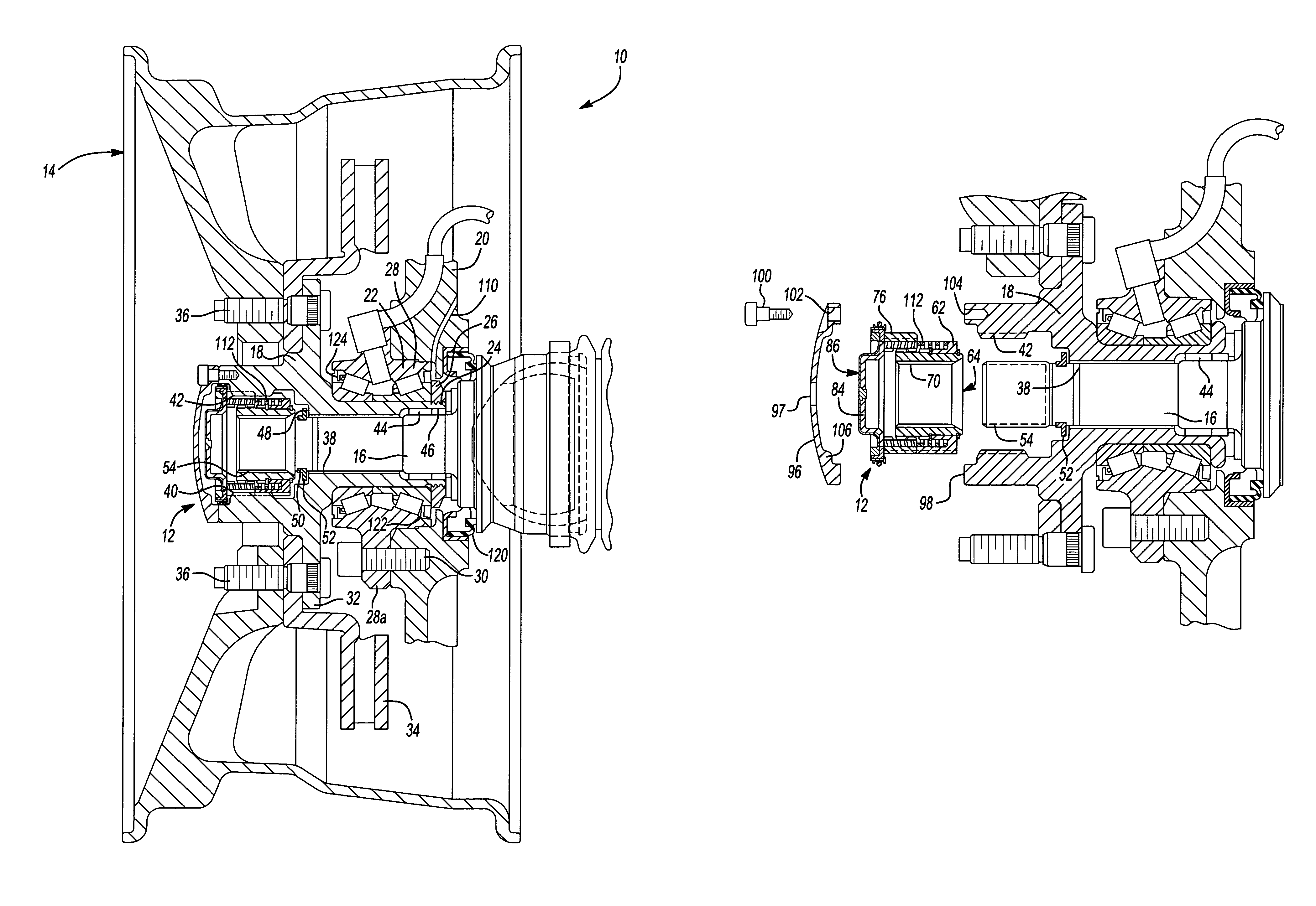
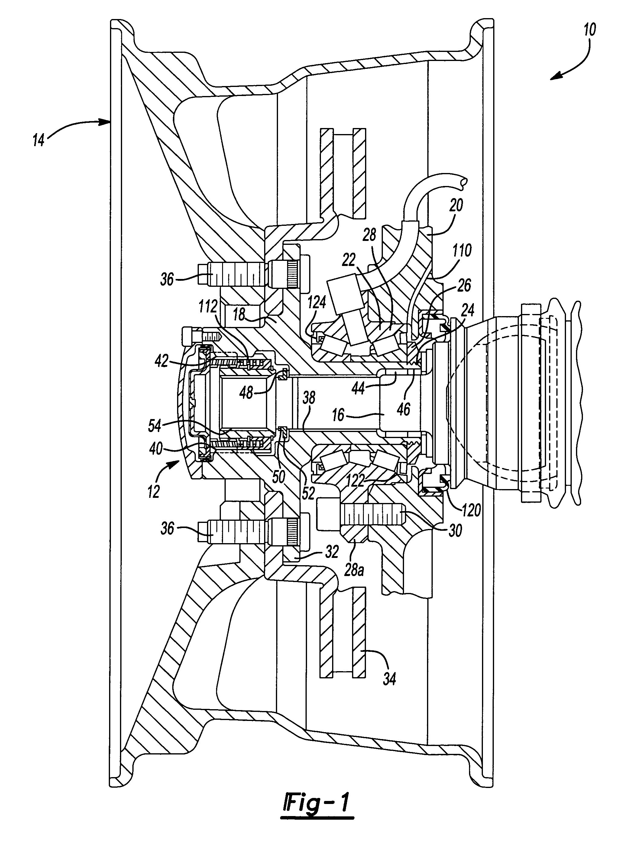
[0012]With reference to FIG. 1, a wheel hub assembly 10 is shown including a vacuum locking hub system 12 that couples a wheel 14 to the axle shaft 16. The wheel 14 is fixedly mounted to a wheel hub 18 which is rotatably supported on the axle shaft 16. It will be understood that the axle 16 and wheel hub 18 can be coupled or uncoupled to one another by the vacuum locking hub system 12.
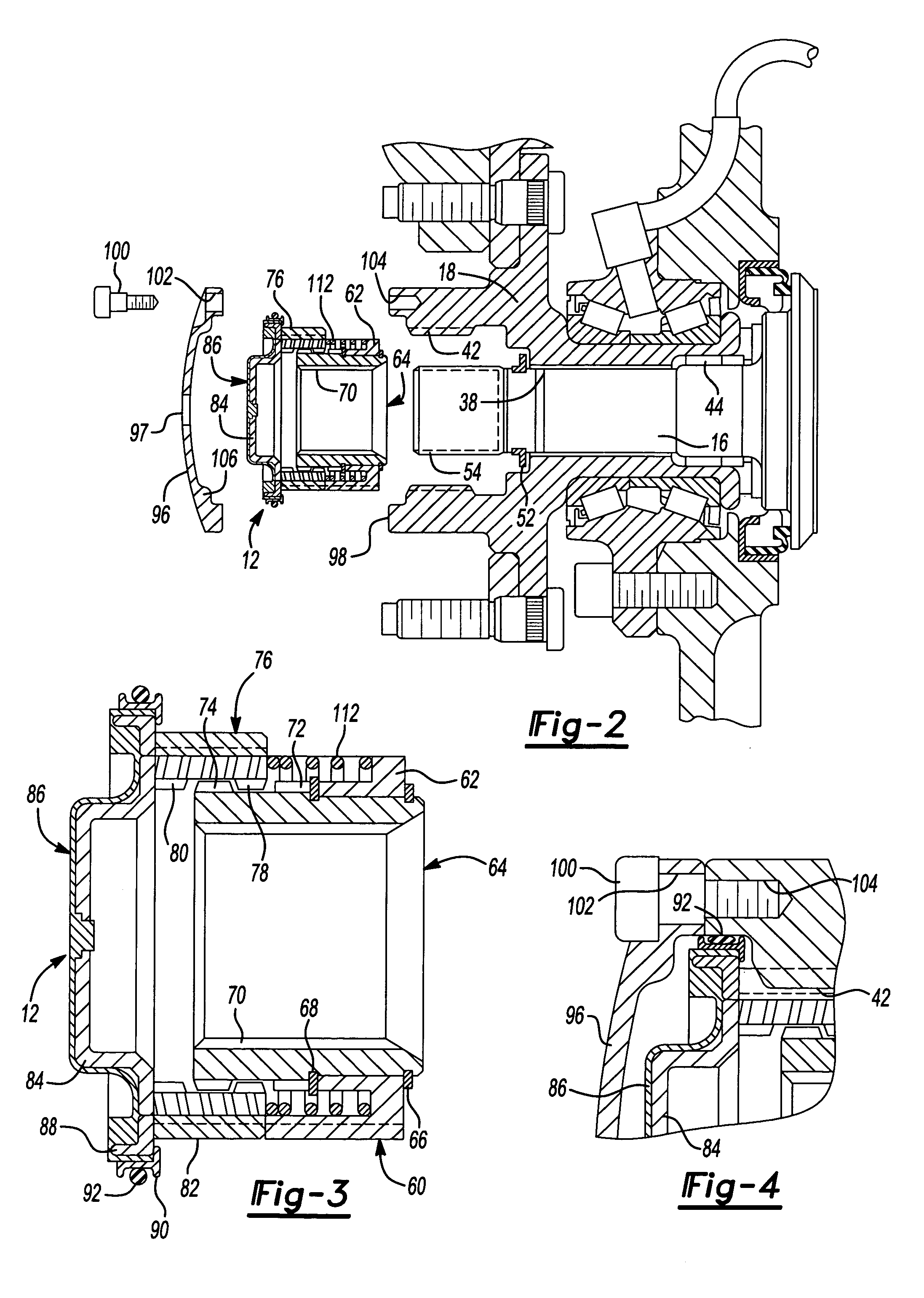
[0013]The wheel hub 18 is supported by a knuckle 20. A bearing assembly 22 is disposed between knuckle 20 and wheel hub 18. Wheel hub 18 includes an inboard end portion 24 which receives either a bearing adjusting nut 26 (as shown in FIG. 1) which is disposed against the bearing assembly 22 or a roll form retention system (as shown in FIG. 2). The bearing assembly 22 includes an outer race portion 28 having an outwardly extending flange ...
PUM
 Abstract
Description
Claims
Application Information