Method and apparatus for operational low-stress optical fiber storage

a technology of optical fiber and storage apparatus, applied in the field of optical fiber, can solve the problems of limited in certain regards, fiber to twist, micro-cracks, etc., and achieve the effects of reducing the torsional force applied, preventing the torsional force and resulting twisting, and reducing the torsional for

Inactive Publication Date: 2006-02-21
LUCENT TECH INC
View PDF10 Cites 93 Cited by
  • Summary
  • Abstract
  • Description
  • Claims
  • Application Information

AI Technical Summary

Benefits of technology

[0007]Therefore, the present inventors have invented a reel for storing optical fiber that significantly reduces the torsional force applied to the fiber as it is being wound onto the reel for storage. Specifically, the present inventors have invented an optical fiber reel that utilizes two spindles that are offset with respect to the rotational center of the reel. Such an arrangement causes the fiber to be wound onto the reel in a substantially linear fashion, thus preventing the torsional force and resulting twisting that cause micro-cracks to develop. Additionally, the spindles are of a sufficiently large diameter to facilitate operational use of the fiber while stored on the spindle without increasing the attenuation of signals that could result from the use of a smaller diameter spindle.

Problems solved by technology

While prior attempts at storing excess fiber between optical components, such as the aforementioned spools, were advantageous in many applications, they were limited in certain regards.
This force tended to cause the fiber to twist as it was being wound onto the spools.
Over time, the stress resulting from this torsional force / twisting caused small cracks, known as micro-cracks, to develop in the optical fiber.
Such micro-cracks tend to increase attenuation of an optical signal when a relatively low power is passed over fiber with such cracks.
However, the problem is much more significant when high-power signals are transmitted over fiber such that, when micro-cracks are present in the fiber, the fiber may actually heat at the location(s) of the micro-cracks to the point of melting.

Method used


Image

  • Method and apparatus for operational low-stress optical fiber storage
  • Method and apparatus for operational low-stress optical fiber storage
  • Method and apparatus for operational low-stress optical fiber storage

Examples


Embodiment Construction

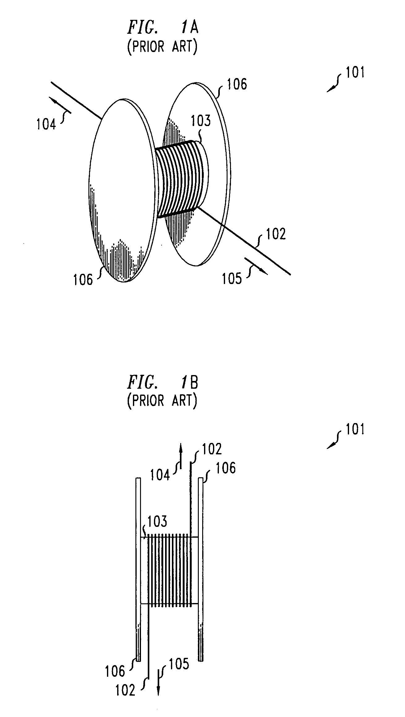
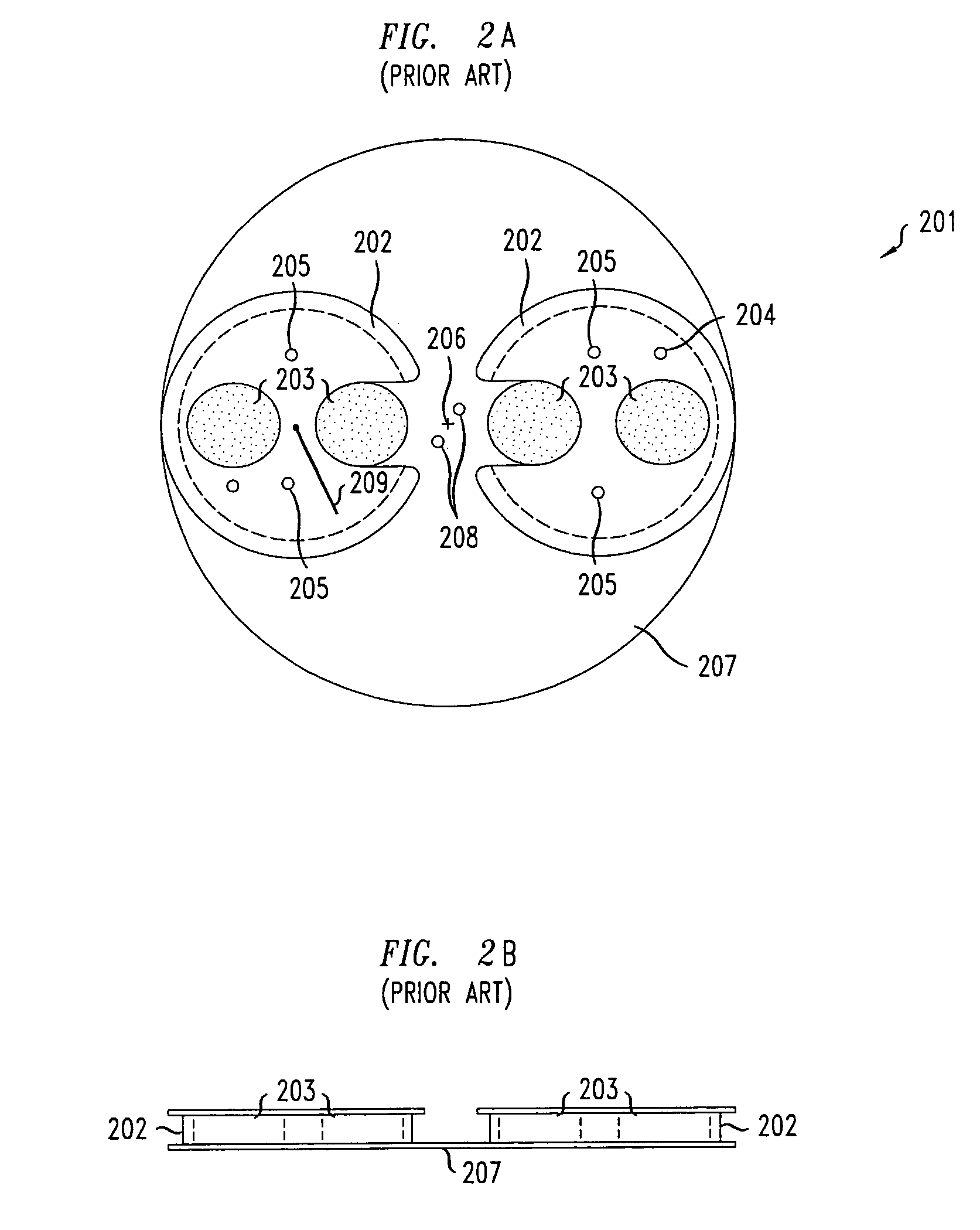
[0015]FIGS. 2A and 2B show a top and a side view, respectively, of an optical fiber reel 201 in accordance with the principles of the present invention. As compared to prior fiber spools, such as that illustrated in FIGS. 1A and 1B, the illustrative reel of FIGS. 2A and 2B is characterized by a support member 207 upon which two optical fiber spindles 202 are mounted. Reel 201 is illustratively manufactured from an aluminum or plastic material, although other materials would be equally advantageous. Spindles 202 have a radius that is sufficient to prevent excessive bending of the optical fiber, exemplarily a radius of ½ of an inch, so that, at relatively high signal powers (e.g., 1 Watt), the signal transmitted over the fiber will not be significantly attenuated. For illustrative purposes, support member 207 is herein shown as a circular disk. One skilled in the art will recognize that many different disk materials, shapes and configurations will be equally advantageous. Illustrative...


PUM


Abstract

A reel for storing optical fiber is disclosed that significantly reduces the torsional force applied to optical fiber as the fiber is being wound onto the reel for storage. The optical fiber reel comprises two spindles that are offset with respect to the rotational center of the reel. Such an arrangement causes the fiber to be wound onto the reel in a substantially linear fashion, thus preventing the torsional force and resulting twisting that cause micro-cracks to develop. The spindles are of a sufficiently large diameter to facilitate operational use of the fiber while stored on the spindle without increasing the attenuation of signals that could result from the use of a smaller diameter spindle.

Description

FIELD OF THE INVENTION[0001]The present invention relates generally to optical fiber and, more particularly, to the storage of optical fiber.BACKGROUND OF THE INVENTION[0002]The use of optical fiber has become widespread in telecommunications applications. Light signals passed along such fiber are capable of extremely high data throughput rates, especially when coupled with throughput optimizing technologies such as dense wavelength division multiplexing (DWDM). Higher throughput over an optical fiber, as is used in long-distance optical transmissions, typically requires a signal with higher power and, accordingly, the fiber must be designed to increasingly stringent design tolerances to accommodate that higher power.[0003]In telecommunications facilities, such as switching facilities, it is often necessary to connect multiple components with lengths of optical fiber. Traditionally, it has been desirable to use the minimum length of fiber necessary to connect the components to avoid...

Claims


Application Information

Patent Timeline
Patent Type & Authority Patents(United States)
IPC IPC(8): G02B6/00B65H75/18G02B6/44
CPCG02B6/4457
Inventor BETHEA, CLYDE GEORGEFRANEY, JOHN PHILIP
Owner LUCENT TECH INC
Why Eureka
Try Eureka