
Method and apparatus for object viewing, observation, inspection, identification, and verification

a technology for object inspection and identification, applied in lighting and heating apparatus, instruments, optical elements, etc., can solve the problems of not being able to discern certain features by people who are not specifically trained, and achieve the effects of convenient use, compact size and low cos

Inactive Publication Date: 2006-02-21
BOCK JOEL N +2
View PDF3 Cites 39 Cited by
  • Summary
  • Abstract
  • Description
  • Claims
  • Application Information

AI Technical Summary

Benefits of technology

[0007]The present invention provides a method and apparatus for object viewing, observation, inspection, identification, and verification that overcomes the limitations of the prior art. More specifically, the present invention provides a method and apparatus for object viewing, observation, inspection, identification, and verification where all of the necessary functions are provided in a single piece of equipment or multiple pieces of equipment operating together, which is of compact size, low cost and easy to use.
[0008]The present invention also provides a method and apparatus for controlled illumination, which may include, for example, control of the wavelength and / or color temperature of a light source. The present invention also provides a method and apparatus for positioning an object, which may include, for example, providing a viewing area that permits the controlled illumination to be the dominant source of light for the object or surface of the object even with relatively high ambient light conditions, and which may also include a positioner for placement and securing of objects, for example, small gem stones, coins, postage stamps, etc. The present invention also provides a viewing window, which may include, for example, the incorporation of selective magnification and which protects the viewer from UV radiation that may be generated by the illumination wavelengths selected.

Problems solved by technology

For example, features in gems, such as, for example, flaws, may be examined and identified using a jeweler's loupe, but certain features may not be discernable by a person not specifically trained or experienced in the use of such a device.

Method used


Image

  • Method and apparatus for object viewing, observation, inspection, identification, and verification
  • Method and apparatus for object viewing, observation, inspection, identification, and verification
  • Method and apparatus for object viewing, observation, inspection, identification, and verification

Examples


Embodiment Construction

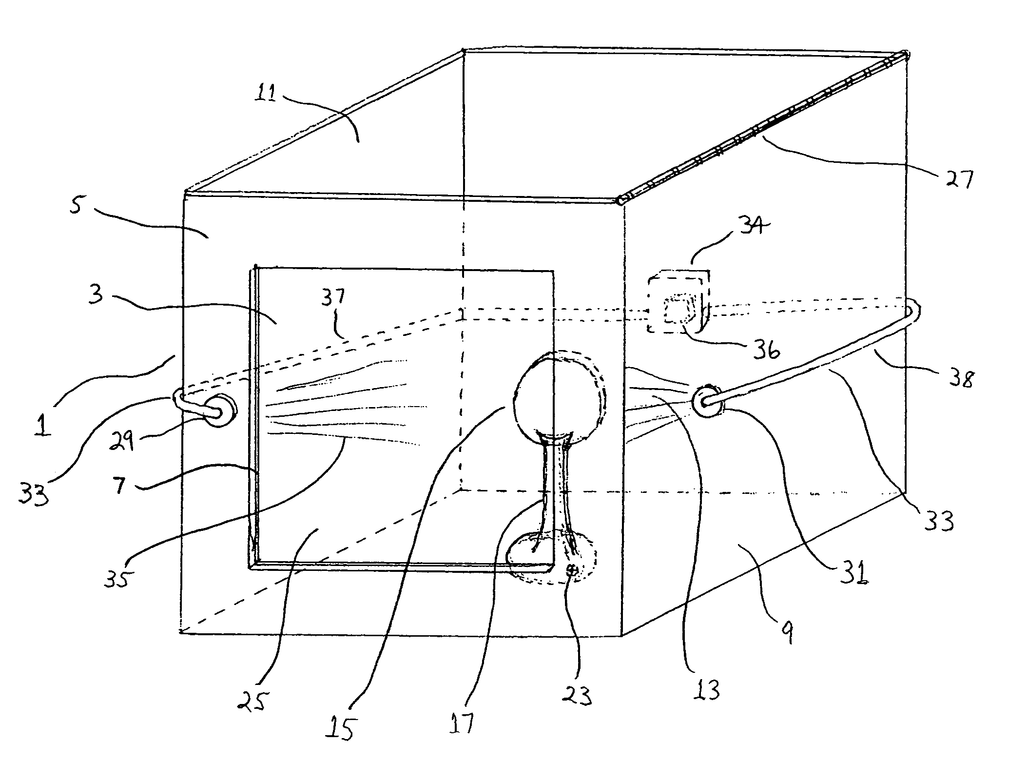
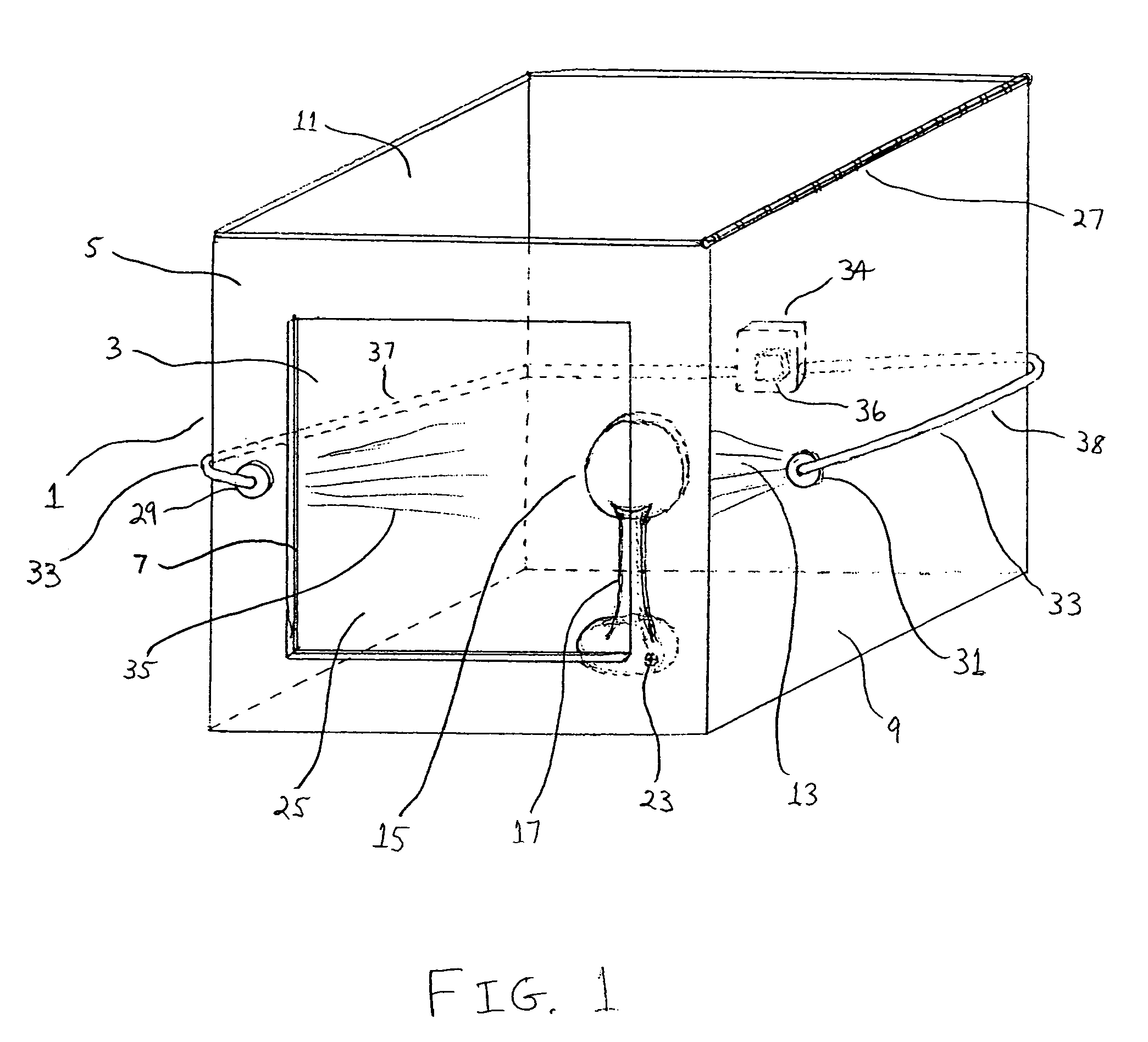
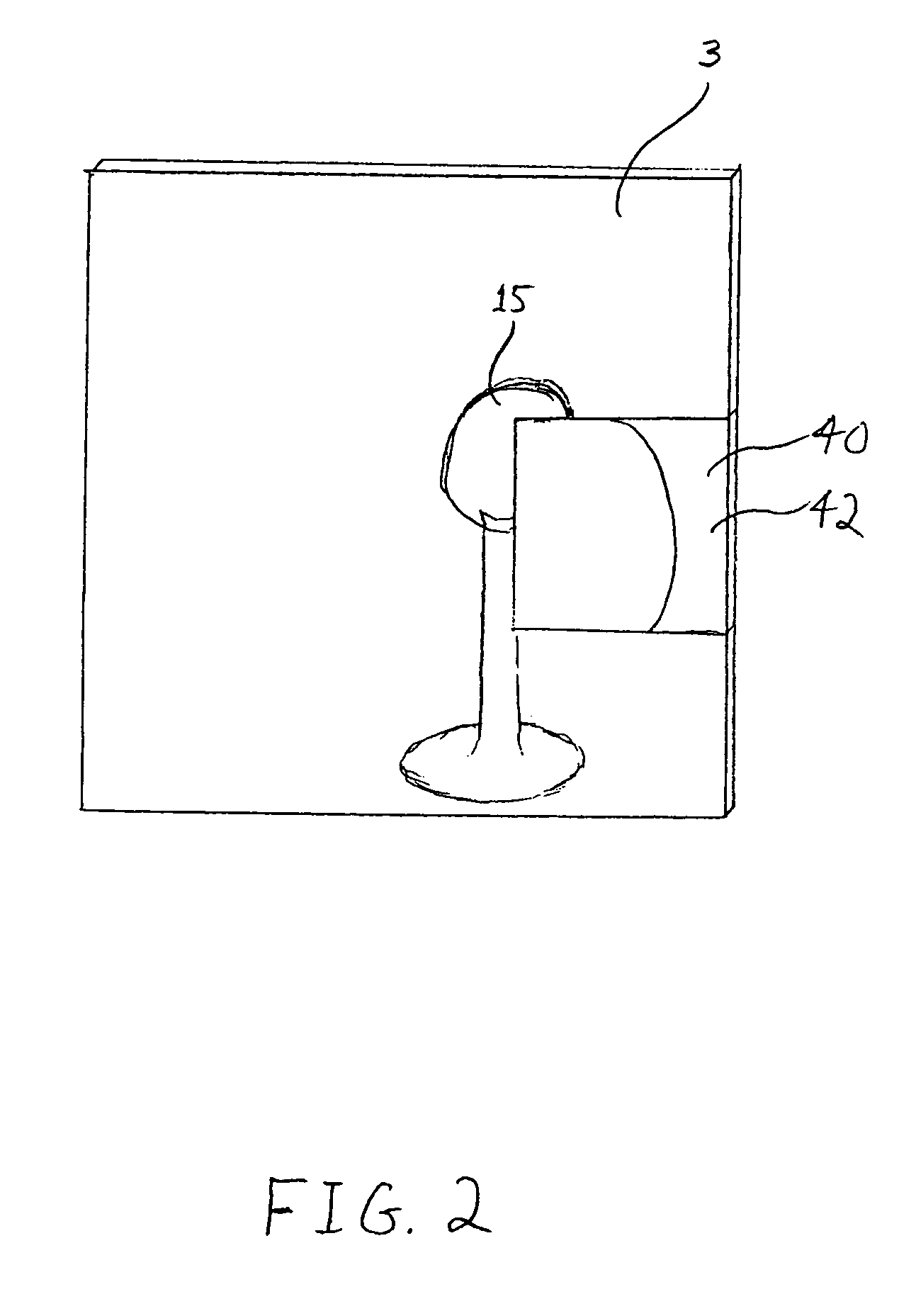
[0052]An exemplified embodiment of an object verifier according the present invention is shown in FIG. 1. This embodiment of a verifier includes a housing 1, in the shape of a cube. Alternatively, the housing may be of any three dimensional shape, including, for example, pyramid, sphere, ovoid, cylinder, octahedron, tetrahedron, polyhedron, spherical, etc., or a portion thereof, for example, a hemisphere. The housing 1 includes a viewing window 3 formed integrally with a first side-wall 5 of the housing 1, or fitted within a frame 7 formed in the first side-wall 5 of the housing 1. The exterior surface of the housing 9, excluding the viewing window 3 may be coated with a protective or decorative material, such as paint, rubber, lacquer, laminate, decals, etc. The interior surfaces of the housing 11 forms an area 13 within which an object 15 is located. The interior surface 11 of the housing, including or excluding the viewing window 3, may be coated with a reflective coating, prefer...


PUM


Abstract

In an object verifier having a housing and an object holder, an object may be placed in the object holder for observation by an operator. The object is illuminated using a collimated beam of white light that is generated by a light generator. The collimated beam of white light is passed through a beam splitter with the two portions of the collimated beam of white light presented to the object at a 90 degree angle one from the other. The interior of the housing includes a reflective surface for maximal illumination of the object. The observer may view the illuminated object through a viewing window and / or through a magnification window. The magnification window provides for the viewing of the object in greater detail.

Description

CROSS-REFERENCE TO RELATED APPLICATION[0001]This application is based on and claims priority from U.S. provisional patent application Ser. No. 60 / 439,368 filed Jan. 10, 2003.FIELD OF THE INVENTION[0002]The present invention relates to a method and apparatus for object viewing, observation, inspection, identification, and verification, and more specifically for the close examination of surfaces or small objects with low power magnification incorporating the use of controlled lighting.BACKGROUND OF THE INVENTION[0003]To determine the authenticity or identify distinguishing features of objects, and specifically of small objects, for example, gem quality stones, or small features on larger objects, for example, water marks on stamps, a number of methods have been used including the use of a jeweler's loupe, a magnifying glass, a microscope, or other similar apparatus, for purposes of magnifying the object or a portion of the object being viewed. The success of these methods depends on a...

Claims


Application Information

Patent Timeline
IPC IPC(8): A47F11/10G01N21/00G01N21/87G02B5/32
CPCG01N21/87F21V15/01G02B5/32G02B5/203
Inventor BOCK, JOEL N.ERICKSON, RONALD R.SANDLER, ELIEZER D.
Owner BOCK JOEL N
Learn More