Adjustable inlay with multizone polymerization

a polymerization and inlay technology, applied in the field of adjustable inlay, can solve the problems of ametropia, inability of the lens and cornea to correctly focus the far point, and inability of the astigmatic eye to sharply focus images on the retina

Inactive Publication Date: 2006-02-21
MINU
View PDF35 Cites 176 Cited by
  • Summary
  • Abstract
  • Description
  • Claims
  • Application Information

AI Technical Summary

Benefits of technology

[0022]An object of the present invention is to provide a system and method for adjusting, without ablation, the size and shape of a blank that has been implanted into a live cornea to modify corneal curvature to thus correct severe ametropic conditions.
[0023]Another object of the invention is to provide a blank that can be implanted into a live cornea to modify corneal curvature to thus correct severe ametropic conditions, and which is modifiable without ablation.
[0025]Still a further object of the present invention is to provide an ablatable implant that can be implanted between layers of the cornea to improve vision in the eye.
[0027]Another object of the present invention is to provide a system and method for adjusting, without ablation, the size and shape of an inlay that has been placed adjacent a surface of the cornea.
[0028]Another object of the present invention is to provide a system and method for adjusting, without ablation, the size and shape of an inlay that has been implanted into a live cornea to modify corneal curvature to thus correct severe ametropic conditions.
[0029]A further object of the present invention is to provide an inlay that can be implanted into a live cornea to modify corneal curvature to thus correct severe ametropic conditions, and which is modifiable without ablation.

Problems solved by technology

However, an eye can have a disorder known as ametropia, which is the inability of the lens and cornea to focus the far point correctly on the retina.
Therefore, an astigmatic eye is incapable of sharply focusing images on the retina.
Although these optical methods can be used to correct vision in eyes suffering from low myopia up to 6 diopters, or in eyes suffering from hypermetropic, hyperopic or astigmatic conditions which are not very severe, that method is ineffective in correcting vision in eyes suffering from sever forms of ametropia.
For example, known optical methods are typically ineffective in correcting high myopia of 6 diopters or greater, and are also ineffective in correcting severe astigmatism and severe forms of hypermetropia or hyperopia.
Altering the shape of the cut portion of the cornea changes the refractive power of this cut portion, which thus affects the location at which light entering the cut portion of the cornea is focused.
However, the technique is impractical because it employs very complicated and time consuming freezing, cutting and thawing processes.
Furthermore, the technique is ineffective in correcting myopic conditions greater than 18 diopters.
However, the keratophakia technique is impractical, complicated, and expensive because it requires manufacturing or cutting a special lens prior to its insertion into the cornea.
Hence, a surgeon is required to either maintain an assortment of many differently shaped lenses, or alternatively, must have access to expensive equipment, such as a cyrolathe, which can be used to cut the lens prior to insertion into the cornea.
However, because only a certain amount of cornea can be ablated without the remaining cornea becoming unstable or experiencing outbulging (eklasia), this technique is not especially effective in correcting very high myopia.
Hence, this procedure typically cannot be effectively used to correct high myopia of greater than 15 diopters because in order to reshape the cornea to the degree necessary to alter its refractive power so as to sufficiently correct the focusing of the eye, too much of the cornea would need to be ablated.
However, this additional surgery can create the risk of damage to the patient's eye, and cause further patient discomfort.

Method used


Image

  • Adjustable inlay with multizone polymerization
  • Adjustable inlay with multizone polymerization
  • Adjustable inlay with multizone polymerization

Examples


Embodiment Construction

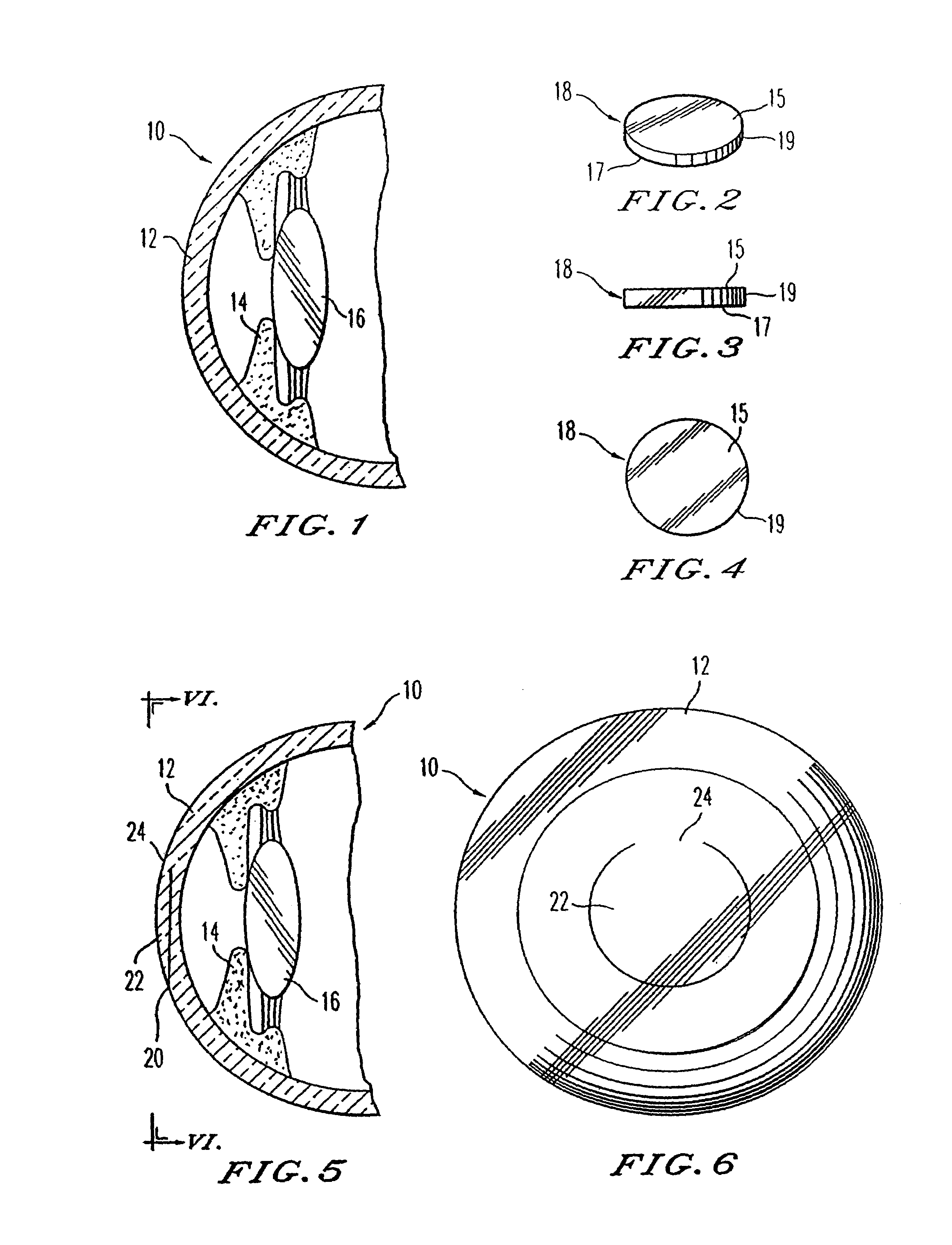
[0094]FIG. 1 is a side elevational view in section taken through the center of an eye 10 which includes a cornea 12, a pupil 14 and a lens 16. If the cornea 12 and lens 16 do not cooperatively focus light correctly on the retina (not shown) of the eye to thus provide adequate vision, the curvature of the cornea can be modified to correct the refractive power of the cornea and thus correct the manner in which the light is focused with respect to the retina.

[0095]A universal blank 18 according to an embodiment of the present invention is illustrated in FIGS. 2–4. As shown, the universal blank according to this embodiment is disk-shaped and has a uniform or substantially uniform thickness throughout, as illustrated specifically in FIG. 3. Specifically, the blank 18 has a first planar or substantially planar surface 15, a second planar or substantially planar surface 17, and a periphery 19. The surfaces 15 and 17 are arranged parallel or substantially parallel to each other with the per...


PUM


Abstract

The present invention relates to an inlay for correcting refractive error in an eye. The inlay includes a first portion having a first volume that remains substantially constant when exposed to an energy, and a second portion having a second volume that is adapted to change when exposed to the energy. This inlay results in a device that can correct severe ametropic conditions, without ablating any portion of the inlay itself or the cornea.

Description

[0001]This application is a continuation-in-part of application Ser. No. 10 / 091,444, filed Mar. 7, 2002, and titled “Adjustable Universal Implant Blank for Modifying Corneal Curvature and Methods of Modifying Corneal Curvature Therewith”, which is a continuation-in-part of application Ser. No. 09 / 532,516, filed Mar. 21, 2000, and titled “An Adjustable Universal Implant Blank for Modifying Corneal Curvature and Methods of Modifying Corneal Curvature Therewith”, now U.S. Pat. No. 6,436,092, the entire contents of both of which are herein incorporated by reference.CROSS-REFERENCE TO RELATED PATENTS AND APPLICATIONS[0002]Related subject matter is disclosed in U.S. Pat. Nos. 5,919,185, 5,722,971 and 4,840,175, in a copending application entitled “A Universal Implant Blank for Modifying Corneal Curvature and Methods of Modifying Corneal Curvature Therewith”, Ser. No. 09 / 260,591, filed Mar. 2, 1999; and in a copending application entitled “Instrastromal Corneal Modification”, Ser. No. 09 / 2...

Claims


Application Information

Patent Timeline
Patent Type & Authority Patents(United States)
IPC IPC(8): A61B18/18A61F2/14A61F9/008A61F9/01
CPCA61F2/147A61F9/00812A61F2009/0088A61F2009/00872A61F9/00836
Inventor PEYMAN, GHOLAM A.
Owner MINU
Why Eureka
Try Eureka