Method of making a needle and a needle

a needle and needle technology, applied in the field of infusion therapy, can solve the problems of affecting the operation of the needle itself, unable to provide a feature that can withstand adequate force without affecting the operation of the needle, and the needle may stick from contaminated introducer needles

Inactive Publication Date: 2006-02-21
BECTON DICKINSON & CO
View PDF33 Cites 34 Cited by
  • Summary
  • Abstract
  • Description
  • Claims
  • Application Information

AI Technical Summary

Benefits of technology

[0007]It is therefore an advantage of one aspect of the instant invention to provide a needle and method of making a needle that may be employed with various safety-engineered shielding devices.
[0009]It is an advantage of another aspect of the instant invention to provide a needle having a sleeve secured to a cannula at a predetermined location and a method for securing the sleeve to the cannula at the predetermined location.
[0010]It is an advantage of yet another aspect of the instant invention to provide a technique for securing a feature on a needle having a sharp, right angled shoulder that can be readily captured by an engaging means in a needle shield and, once captured, can direct the forces from the engaging means to the needle in a substantially axial direction.

Problems solved by technology

Although clinicians are aware of the need to properly handle “blood contaminated sharps,” in certain medical environments, such as emergency situations or as a result of inattention or neglect, needle sticks from contaminated introducer needles may occur.
Due to the small size of the needle and its delicate structure, it has been difficult to provide a feature that can withstand adequate force without affecting the operation of the needle itself.
Further, such features have traditionally included a ramp, a radius or angled surface extending from the surface of the needle that may create difficulty in capturing the tip within the shield or may result in exertion of force on the needle in a non-axial direction.

Method used


Image

  • Method of making a needle and a needle
  • Method of making a needle and a needle
  • Method of making a needle and a needle

Examples


Embodiment Construction

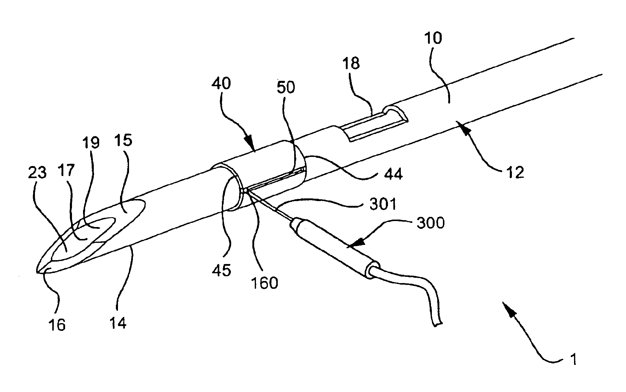
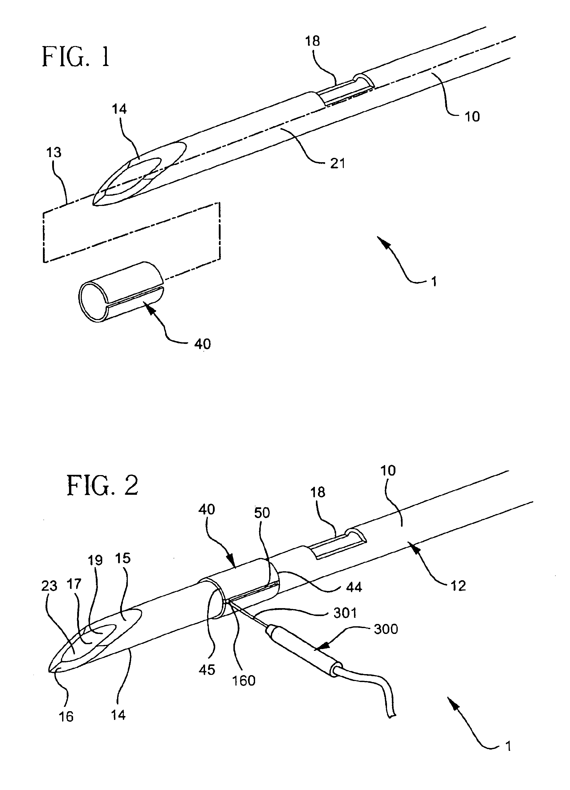
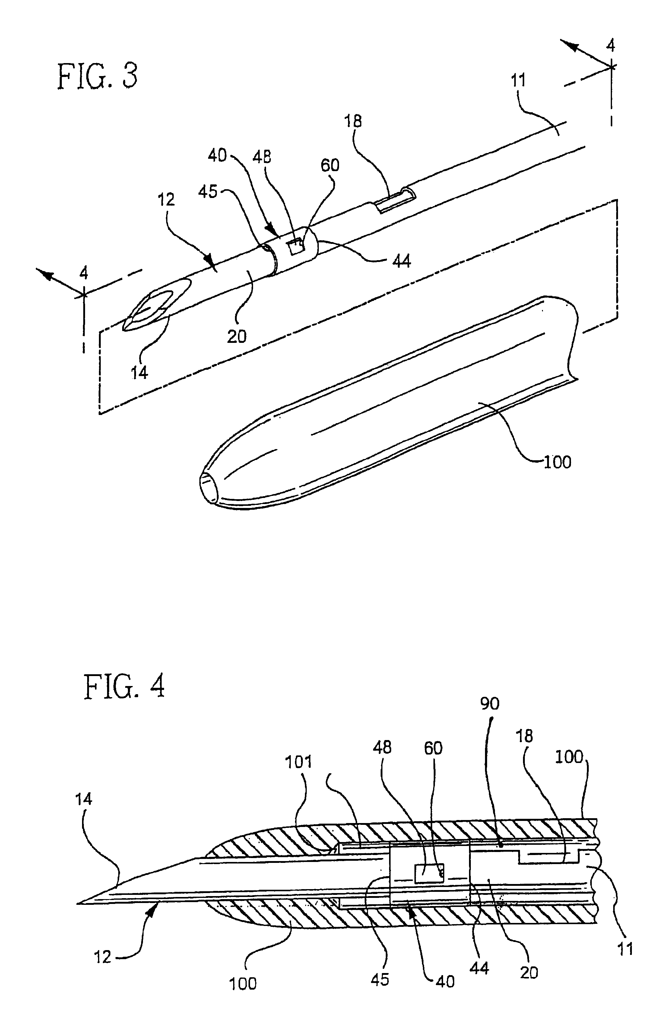
[0031]As used herein, the term “proximal” refers to a location on the needle 1 that, during normal use, is closest to the clinician using the device and farthest from the patient in connection with whom the device is used (the right side of FIG. 4). Conversely, the term “distal” refers to a location on the needle that, during normal use, is farthest from the clinician using the device and closest to the patient in connection with whom the device is used (the left side in FIG. 4).

[0032]In various stages of the manufacture of needle assemblies and during the use of needles, it would be advantageous to have a distinct feature on the needle 1 that is secured at a fixed location and orientation with respect to the rest of the needle 1, particularly the tip 14. For example, such a feature may be employed to orient the needle 1 with respect to a needle hub or holder. Consequently, the needle tip 14 would also be at a fixed orientation with respect to the holder. A caregiver would thus know...


PUM

PropertyMeasurementUnit
outer diameteraaaaaaaaaa

Abstract

A method is provided for forming a feature on a needle. In particular, a hollow, metal cannula has a first end, a second end and a substantially constant outer diameter extending over at least a portion of its length. An annular metal sleeve is provided that has a proximal shoulder and a distal shoulder. The length of the annular sleeve is less than the length of the constant diameter portion of the cannula. The sleeve has an inner diameter approximately equal to or less than the outer diameter of the constant diameter portion of the cannula. Two edges extend axially along the length of the sleeve, from the proximal shoulder to the distal shoulder, thereby defining a slit. The sleeve is positioned on the cannula at the constant outer diameter portion in an interference fit. An additional mechanical junction may be provided to secure the sleeve to the cannula. For example, the sleeve may be welded to the cannula using a laser welder at at least one edge of the sleeve near one of either the proximal face or the distal face. Alternatively and additionally, the sleeve may be crimped or glued to the cannula. In accord with another aspect of this invention, a needle is provided made in accord with this method.

Description

[0001]This application is a continuation of application Ser. No. 10 / 137,464 filed May 1, 2002.FIELD OF THE INVENTION[0002]The subject invention relates to the field of infusion therapy. In particular, the invention is related to an introducer needle having a shoulder disposed at a predetermined distance from the tip of the needle and to a method for making such a needle.BACKGROUND OF THE INVENTION[0003]Catheters, particularly intravenous (IV) catheters, are used for infusing fluid, such as normal saline solution, various medicaments and total parenteral nutrition, into a patient or withdrawing blood from a patient. Peripheral IV catheters tend to be relatively short, and are on the order of about one and one-half inches in length. The most common type of IV catheter is an over-the-needle peripheral IV catheter. As its name implies, an over-the-needle catheter is mounted over an introducer needle having a sharp distal tip. The catheter and the introducer needle are assembled so that ...

Claims


Application Information

Patent Timeline
Patent Type & Authority Patents(United States)
IPC IPC(8): B23K26/00A61M5/32A61M25/00A61M25/08B21C37/08B21G1/08
CPCA61M5/3273A61M5/3286B21G1/08B21C37/0815A61M5/329
Inventor ADAMS, CHAD MICHAEL
Owner BECTON DICKINSON & CO
Why Eureka
Try Eureka