
Superconducting quantum interference apparatus and method for high resolution imaging of samples

a quantum interference and superconducting technology, applied in the direction of superconducting devices, magnetic field measurement, instruments, etc., can solve the problems of limited scanning squid microscopes, patents that do not disclose the manner in which the sensor is used, and the adjustment apparatus does not lend itself to extremely close tolerance spacing

Inactive Publication Date: 2006-02-21
VANDERBILT UNIV +1
View PDF21 Cites 28 Cited by
  • Summary
  • Abstract
  • Description
  • Claims
  • Application Information

AI Technical Summary

Problems solved by technology

Such an adjustment apparatus does not lend itself to extremely close tolerance spacing between the SQUID sensor and the sample.
Another problem associated with the patented systems is that with such close tolerance spacing, it is important to maintain the window of the SQUID and the platform for supporting the room-temperature sample in a parallel relationship.
Also, the patents do not disclose the manner in which the sensor is connected or matched to the system to provide the desired high resolution imaging.
article). Scanning SQUID microscopes are limited by the often-conflicted demands for high field sensitivity, which requires large sensing volumes and low noise SQUIDs, and high spatial resolution, requiring small sensing volumes, in close proximity to t
Unfortunately, HTS SQUIDs may suffer from excess 1 / f noise associated with flux motion in the bulk superconductor and critical current fluctuations in the Josephson junctions (see the Dantsker, et al. article).
Hence HTS SQUIDs have not yet always provided the combined low-frequency sensitivity and high spatial resolution required for magnetic imaging of many applications, such as bioelectric currents in living tissue and weak remnant magnetization in geological specimens.
These numbers suggest that the thermal design for an LTS microscope is only slightly more challenging than for an HTS SQUID microscope.

Method used


Image

  • Superconducting quantum interference apparatus and method for high resolution imaging of samples
  • Superconducting quantum interference apparatus and method for high resolution imaging of samples
  • Superconducting quantum interference apparatus and method for high resolution imaging of samples

Examples


first embodiment

[0160]The first embodiment is the use of a small diameter (1 mm) magnetometer or gradiometer to allow imaging of object features <100 μm in size. An advantage of an axial gradiometer (e.g., FIGS. 15 and 17) is its ability to preferentially reject signals from distant noise sources. A relative disadvantage of multi-turn coils wound on a fixed diameter mandrel is that the coils are sequentially layered above the bottom coils or wound as a solenoid. In either case, the structure becomes three dimensional (non-flat) with the upper turns be located further from the object being detected.

second embodiment

[0161]the detection coil is the use of a fractional turn SQUID (FIG. 32), [“Sensitivity enhancement of superconducting quantum interference devices through the use of fractional-turn loops”, J. E. Zimmerman, J. Appl Phys, vol 42, pp 4483–4487 (1971)] in place of the combined SQUID sensor and separate detection coils or integrated SQUID sensor / magnetometer. Rather than having a single superconducting SQUID loop (FIG. 33), a fractional turn SQUID connects N loops in parallel (FIG. 34) reducing the total inductance of the SQUID while keeping the effective area constant. This gives rise to higher sensitivity for a fixed diameter. Additionally, its planar fabrication places the sensing element closer to the object being detected that a three dimensionally multi-turn or solenoidally wound magnetometer or gradiometer. Axial (e.g., dBz / dz) or planar (e.g., dBz / dx) gradiometers can be synthesized by appropriately positioning two or more fractional turn SQUIDs and electronically subtracting t...

third embodiment

[0162]the detection coil is the use of an apodized or spiral detection coils [U.S. Pat. No. 5,038,104 “Magnetometer flux pick-up coil with non-uniform interturn spacing optimized for spatial resolution”, John Wikswo, Jr., and Bradley J. Roth (1991)] (FIG. 20). The advantage of an apodized coils is greater spatial resolution than a multi-turn coil of the same outer diameter that has been wound on a fixed diameter mandrel (necessitating that the additional turns be wound sequentially above the lowest coil).

[0163]Like the fractional turn SQUID, planar fabrication places the sensing element closer to the abject being detected that a three dimensionally multi-turn or solenoidally wound magnetometer or gradiometer. Apodized coils lend themselves to the creation of intrinsic axial gradiometers while retaining their minimum vertical thickness.


PUM


Abstract

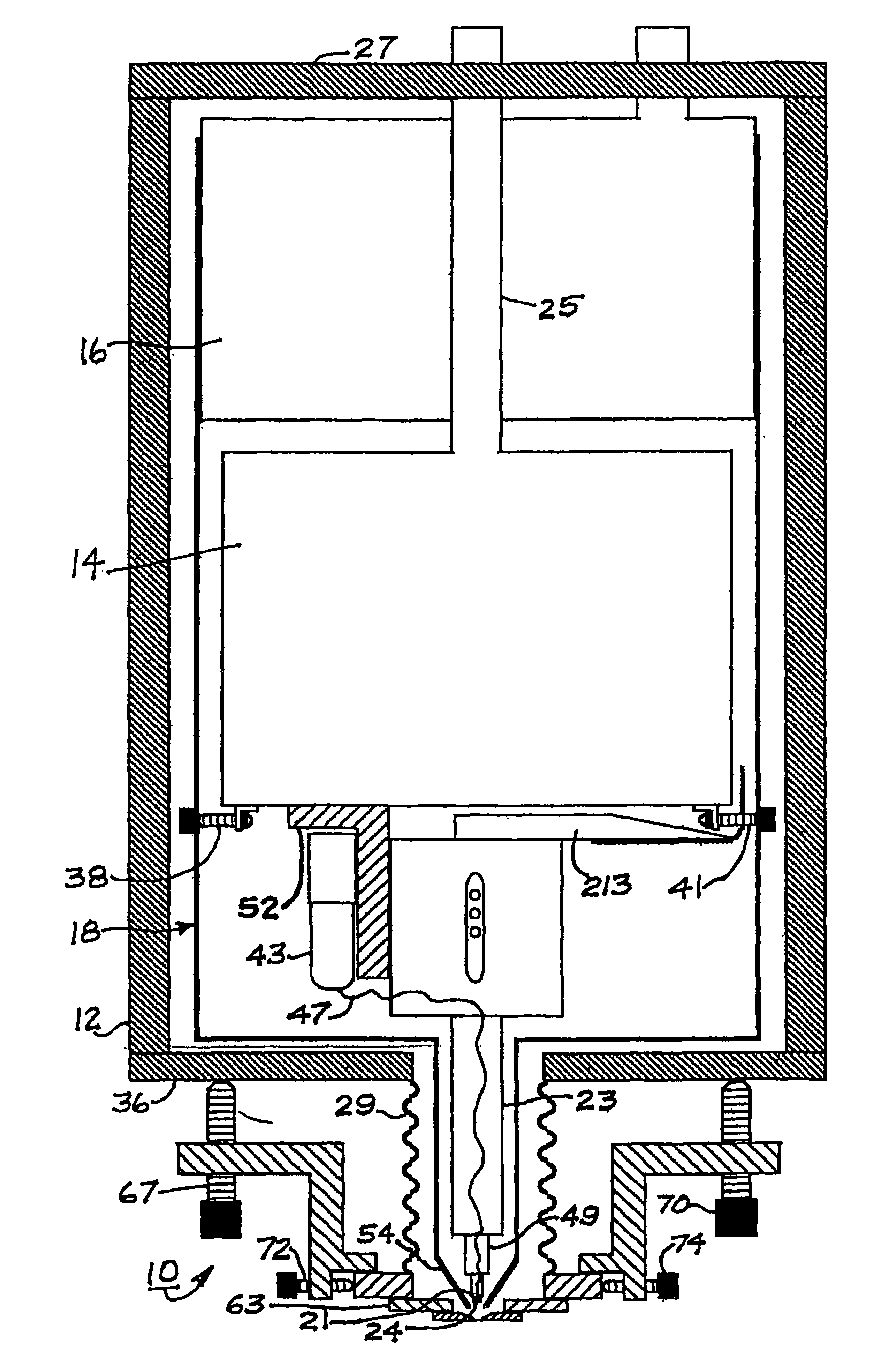
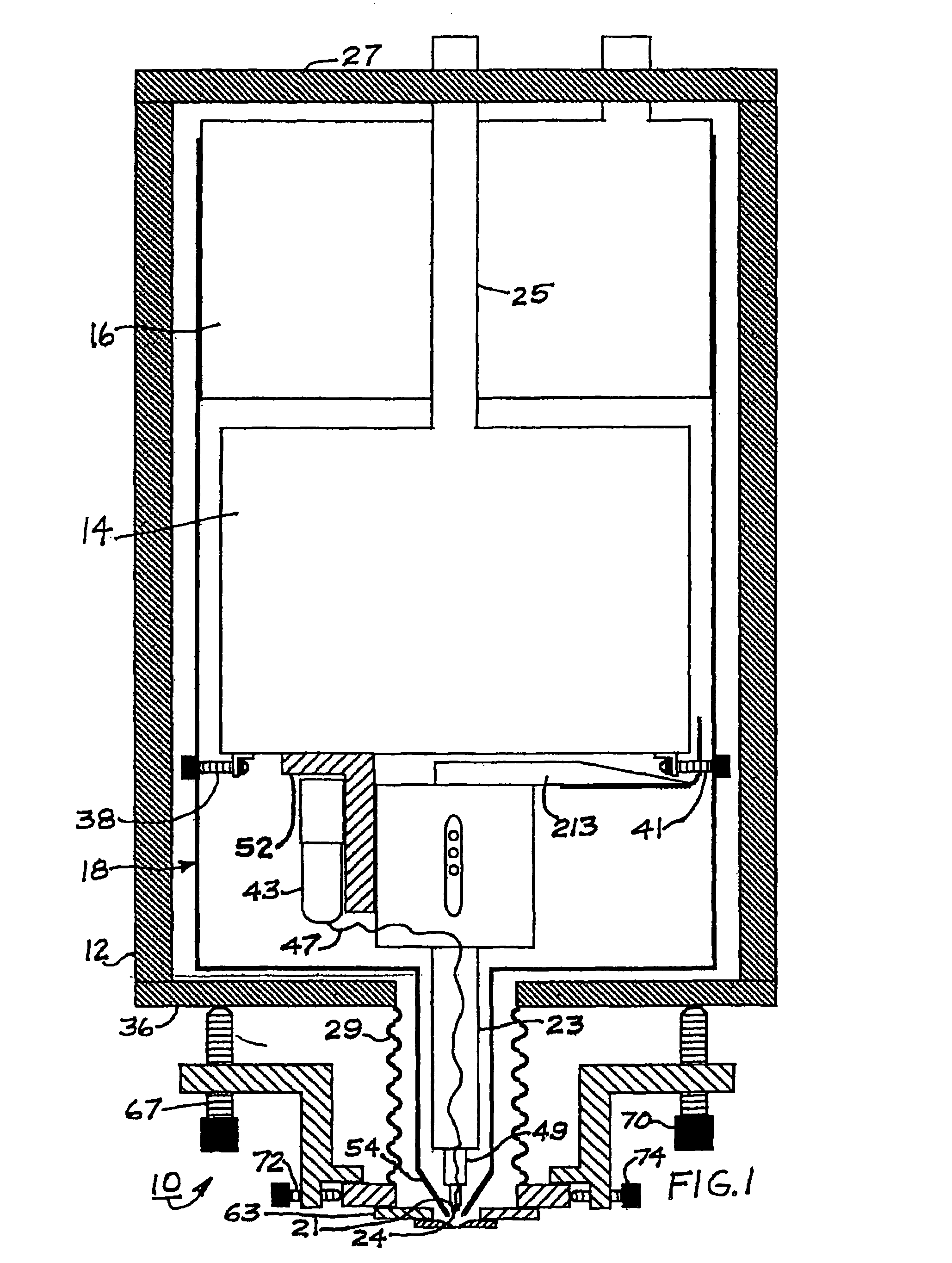
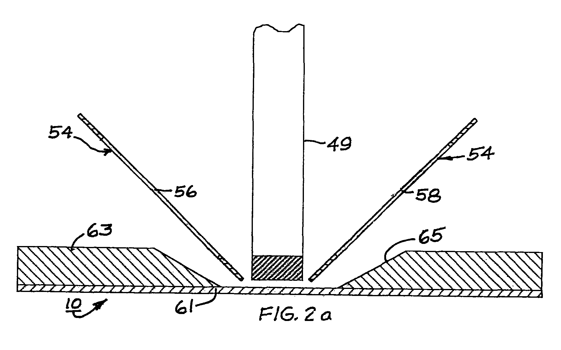
A method and apparatus performs high resolution imaging. The disclosed apparatus includes a low temperature SQUID sensor mounted in close proximity to a dewar thin window. A radiation shield has an extension surrounding the detection coil.

Description

RELATED APPLICATIONS[0001]This application claims priority to U.S. provisional application Ser. No. 60 / 407,417 abandoned, filed Aug. 28, 2002, entitled METHOD AND APPARATUS FOR HIGH RESOLUTION IMAGING OF SAMPLES USING SUPERCONDUCTING QUANTUM INTERFERENCE DEVICES, which is incorporated herein by reference in its entirety.BACKGROUND OF THE INVENTION[0002]1. Field of the Invention[0003]The present invention related to methods and apparatus for high resolution imaging of samples using a superconductive quantum interference device (SQUID).[0004]2. Background Art[0005]This section describes the background of the disclosed embodiments of the present invention. There is no intention, either expressed or implied, that the background art discussed in this section legally constitutes prior art.[0006]There have been a variety of different types and kinds of devices for imaging samples. One example of apparatus and methods used for high resolution imaging employs superconducting quantum interfer...

Claims


Application Information

Patent Timeline
IPC IPC(8): G01R33/02G01R33/035
CPCG01R33/0354
Inventor BAUDENBACHER, FRANZ J.PETERS, NICHOLAS T.WIKSWO, JR., JOHN P.FAGALY, ROBERT L.
Owner VANDERBILT UNIV
Learn More