
Power supply controlling device of an electronic equipment

a technology of power supply control and electronic equipment, which is applied in the direction of electric variable regulation, process and machine control, instruments, etc., can solve the problems of unfavorable printing, unfavorable printing, and unfavorable printing. , to achieve the effect of reducing the withstanding voltage of the switch and reducing the power consumption of the electronic equipmen

Inactive Publication Date: 2006-02-21
HEWLETT PACKARD DEV CO LP
View PDF18 Cites 26 Cited by
  • Summary
  • Abstract
  • Description
  • Claims
  • Application Information

AI Technical Summary

Benefits of technology

[0009]According to an aspect of the present invention, there is provided a power supply controlling device of an electronic equipment, which can reduce a withstanding voltage of a switch capable of performing an on / off operation to supply power to the electronic equipment and can reduce a power consumption of the electronic equipment when the electronic equipment is not operated.

Problems solved by technology

However, because the printer is utilized only when performing a printing operation on the printing data, the printer consumes undesirable power when not performing the printing operation in a power-on status.
However, also in this case, the power consumption occurs.
However, supplying the power supply switch is not cost efficient because the power supply switch that needs to be provided should withstand an input of a few hundreds volts.

Method used


Image

  • Power supply controlling device of an electronic equipment
  • Power supply controlling device of an electronic equipment
  • Power supply controlling device of an electronic equipment

Examples


Embodiment Construction

[0020]Reference will now be made in detail to the aspects of the present invention, examples of which are illustrated in the accompanying drawings, wherein like reference numerals refer to like elements throughout. The aspects are described below in order to explain the present invention by referring to the figures.

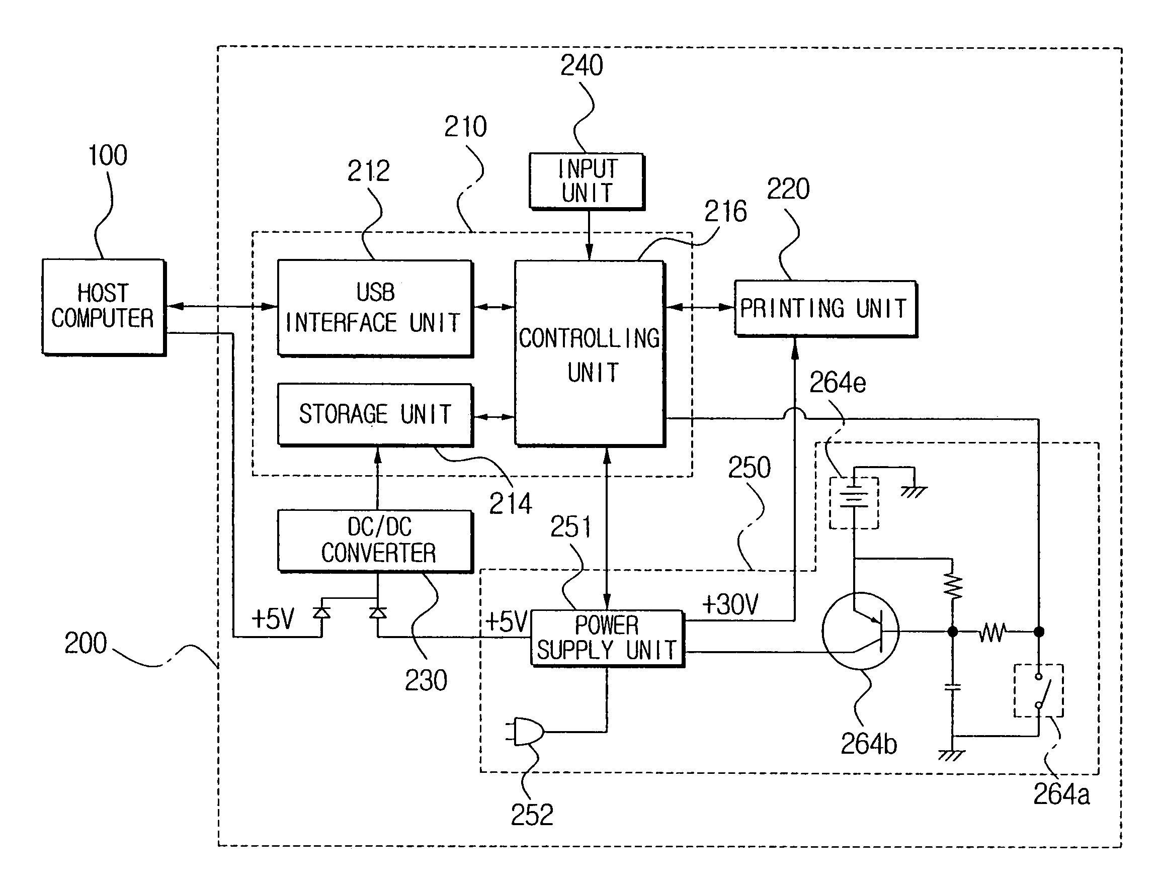
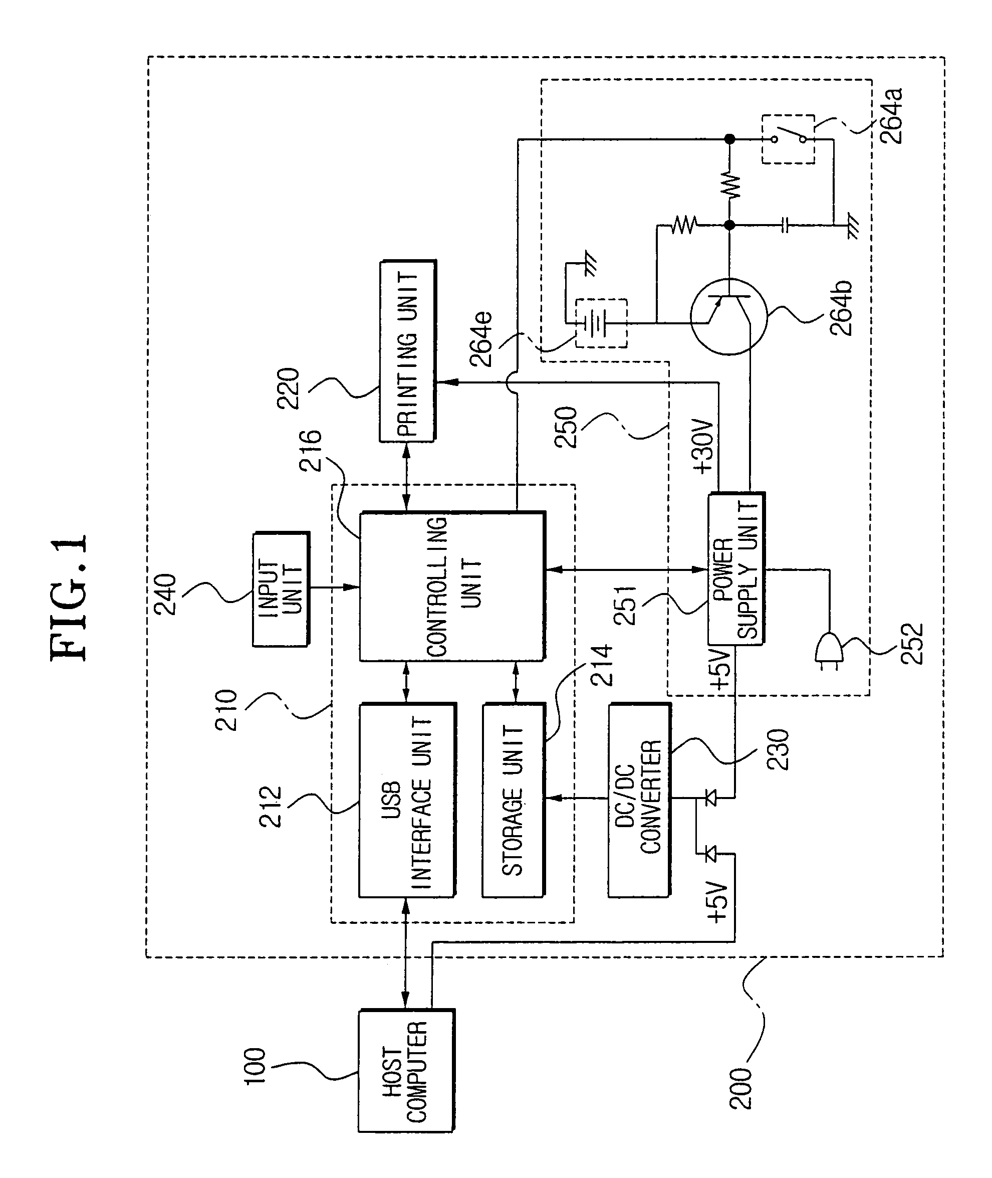
[0021]FIG. 1 is a block diagram of a printer system including a power supply controlling device, according to an aspect of the present invention.

[0022]With reference to FIG. 1, the printer system includes a host computer 100 and a printer 200.

[0023]The host computer 100 transmits printing data to the printer 200, a signal to control the printer 200 such as a printing command, and a predetermined amount of power to drive a signal processing unit 210 of the printer 200.

[0024]The printer 200 performs a printing operation of the printing data in response to the printing command received from the host computer 100.

[0025]The printer 200 includes the signal processing unit 210, ...


PUM


Abstract

A system connecting a printer and a host computer includes a signal processing unit, a printing unit, a DC / DC converter converting a power supply voltage into a lower voltage required by the signal processing unit and outputting the converted voltage to the signal processing unit, an input unit receiving a printing command, and a power supply controlling device. The power supply controlling device includes a first switching unit, a pulse width modulating unit, a power supply switch providing a power on / off signal from a user, and a power supply controlling unit outputting a control signal to the pulse width modulating unit to control the first switching unit to perform an on / off operation corresponding to the power on / off signal from the user.

Description

CROSS-REFERENCE TO RELATED APPLICATIONS[0001]This application claims the benefit of Korean Application No. 2002-43416, filed Jul. 23, 2002, in the Korean Intellectual Property Office, the disclosure of which is incorporated herein by reference.BACKGROUND OF THE INVENTION[0002]1. Field of the Invention[0003]The present invention relates to a power supply controlling device of an electronic equipment, and more particularly, relates to a power supply controlling device of an electronic equipment capable of controlling power which is supplied thereto.[0004]2. Description of the Related Art[0005]A printer is a device for printing data received from a computer connected thereto onto sheets using ink or toner, etc.[0006]However, because the printer is utilized only when performing a printing operation on the printing data, the printer consumes undesirable power when not performing the printing operation in a power-on status.[0007]Furthermore, because a power supply of a conventional printe...

Claims


Application Information

Patent Timeline
Patent Type & Authority Patents(United States)
IPC IPC(8): H02M3/335G06F1/26H02M1/00H02M1/36
CPCH02M1/36G06F1/26H02M3/335
Inventor KIM, JUNG-HWANCHOI, KYUNG-CHOOL
Owner HEWLETT PACKARD DEV CO LP
Learn More