Plasma display panel, and apparatus and method for driving the same

Inactive Publication Date: 2005-05-12
SAMSUNG SDI CO LTD
View PDF16 Cites 10 Cited by
  • Summary
  • Abstract
  • Description
  • Claims
  • Application Information

AI Technical Summary

Benefits of technology

[0018] Therefore, it is an aspect of the present invention to provide an apparatus for driving a plasma display panel, wherein tw

Problems solved by technology

In order to withstand this high voltage, it is necessary to use a switch with a high

Method used


Image

  • Plasma display panel, and apparatus and method for driving the same
  • Plasma display panel, and apparatus and method for driving the same
  • Plasma display panel, and apparatus and method for driving the same

Examples


first embodiment

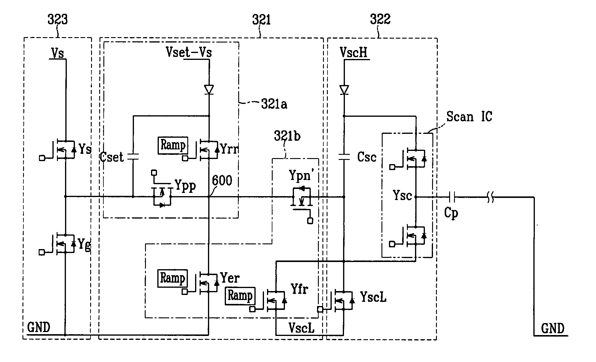
[0046]FIG. 6 is a detailed circuit diagram of a Y electrode driver (e.g., the driver 320 of FIG. 5) of a PDP (e.g., the PDP of FIG. 5) according to the present invention.

[0047] As shown in FIG. 6, the Y electrode driver (e.g., the driver 320 of FIG. 5) according to the first embodiment of the present invention includes a reset driver 321, a scan driver 322 and a sustain driver 323.

[0048] The reset driver 321 includes a rising ramp generator 321a for generating a rising reset waveform in a reset period and a falling ramp generator 321b for generating a falling reset waveform in the reset period.

[0049] The rising ramp generator 321a includes a voltage source Vset−Vs, a capacitor Cset for operating with a floating voltage, a ramp switch Yrr, and a switch Ypp formed on a main path for preventing a reverse flow of current. The falling ramp generator 321b includes a ramp switch Yfr connected to a voltage source VscL, and a switch Ypn′ formed on the main path for preventing a reverse flo...

second embodiment

[0062] Referring to FIG. 8, the present invention provides a PDP driving apparatus including a falling ramp generator 321c which is capable of lowering both the withstand voltages of switches Ypn″ and Yer′.

[0063]FIG. 8 is a detailed circuit diagram of a Y electrode driver (e.g., driver 320 of FIG. 5) including a reset driver 321′, a scan driver 322′ and a sustain driver 323′.

[0064] The reset driver 321′ includes the falling ramp generator 321c for generating a falling reset waveform in a reset period and a rising ramp generator 321a′ for generating a rising reset waveform in a reset period.

[0065] As shown in FIG. 8, the falling ramp generator 321c according to the second embodiment of the present invention includes a ramp switch Yer′ connected between the constant-voltage capacitor Cset of the rising ramp generator 321a′ and the ground terminal GND for generating a falling ramp waveform of the first step that falls from the voltage Vs to 0V, a ramp switch Yfr connected between the...


PUM


Abstract

An apparatus and method for driving a plasma display panel and includes two ramp switches. The two ramp switches are used to apply a two-step falling ramp waveform to a Y electrode of the plasma display panel in a reset period, thereby lowering a withstand voltage of a switch which is formed on a main path to block the flow of current when the falling ramp waveform is applied.

Description

CROSS REFERENCE TO RELATED APPLICATION [0001] This application claims priority to and the benefit of Korean Patent Application No. 10-2003-0079107 filed on Nov. 10, 2003, in the Korean Intellectual Property Office, the entire content of which is incorporated herein by reference. BACKGROUND OF THE INVENTION [0002] (a) Field of the Invention [0003] The present invention relates to an apparatus and method for driving a plasma display panel (PDP). [0004] (b) Description of the Related Art [0005] Recently, a PDP is being highlighted as a flat panel display in that it is advantageous over the other flat panel displays in regard to its high luminance, high luminous efficiency and wide viewing angle. [0006] The PDP is a flat panel display that uses plasma generated by gas discharge to display characters or images. According to its size, the PDP can include tens to millions of pixels arranged in the form of a matrix. The structure of the PDP will now be described with reference to FIGS. 1 an...

Claims


Application Information

Patent Timeline
IPC IPC(8): G09G3/20G09F9/313G09G3/288G09G3/291G09G3/292G09G3/293G09G3/294G09G3/296G09G3/298H01J17/49
CPCG09G3/2927G09G2310/066G09G3/296
Inventor LEE, JOO-YUL
Owner SAMSUNG SDI CO LTD
Why Eureka
Try Eureka