Resonant inverter and isolated resonant power supply device

a power supply device and inverter technology, applied in the direction of electric variable regulation, process and machine control, instruments, etc., can solve the problems of difficult driving of high-side switches such as bridge circuits, large number of adjustment parts, and large voltage ranges, so as to reduce the operating voltage of the first switch or the second switch, the effect of reducing the cost of the circuit and the device, and prolonging the life of the switch

Active Publication Date: 2016-11-17
TDK CORPARATION
View PDF4 Cites 6 Cited by
  • Summary
  • Abstract
  • Description
  • Claims
  • Application Information

AI Technical Summary

Benefits of technology

[0014]Accordingly, the turns ratio of the transformer can be determined independently of the resonant rectifier on the secondary side. Further, the first resonant circuit and the second resonant circuit are configured by using the leakage inductance of the transformer. As a result, it is possible to eliminate the first coil and the second coil, and to achieve downsizing and cost reduction of the circuit and device.
[0015]In the resonant inverter described above, at least three resonance points may be generated in response to resonance of the first resonant circuit, the second resonant circuit, and the fifth resonant circuit, the three resonance points including a first resonance point, a second resonance point, and a third resonance point, and if a lowest resonance frequency that corresponds to the first resonance point is denoted by F1, a highest resonance frequency that corresponds to the third resonance point is denoted by F3, the second resonance point that corresponds to a resonance frequency between F1 and F3 is fixed, and a drive frequency for driving the first switch or the second switch is denoted by Fs, then, 1Fs≦(F3−F1)<2Fs may be satisfied. Accordingly, the operating voltage of the first switch or the second switch can be decreased. As a result, the life of the switch can be extended.
[0016]In the resonant inverter described above, at least three resonance points may be generated in response to resonance of the first resonant circuit, the second resonant circuit, and the third or fourth resonant circuit, the three resonance points including a first resonance point, a second resonance point, and a third resonance point, and if a lowest resonance frequency that corresponds to the first resonance point is denoted by F1, a highest resonance frequency that corresponds to the third resonance point is denoted by F3, the second resonance point that corresponds to a resonance frequency between F1 and F3 is fixed, and a drive frequency for driving the first switch or the second switch is denoted by Fs, then, 1Fs≦(F3−F1)<2Fs may be satisfied. Accordingly, the operating voltage of the first switch or the second switch can be decreased. As a result, the life of the switch can be extended.
[0017]According to the aspects of the present invention, it is possible to provide a resonant inverter and an isolated resonant power supply device for which the resonance frequencies can be easily adjusted, the life of the switch can be extended by decreasing the operating voltage of the switch, and downsizing and cost reduction of the device can be achieved.

Problems solved by technology

In general, in a high-frequency inverter, driving a high-side switch, such as a bridge circuit, at a high frequency is difficult from the viewpoint of preventing a flow-through current between the high-side switch and a low-side switch because a short dead time needs to be assured.
As a result, the resonance condition setting and the output voltage range vary, which is an issue.
As a result, adjustments need to be made on a large number of portions, which is also an issue.

Method used


Image

  • Resonant inverter and isolated resonant power supply device
  • Resonant inverter and isolated resonant power supply device
  • Resonant inverter and isolated resonant power supply device

Examples


first embodiment

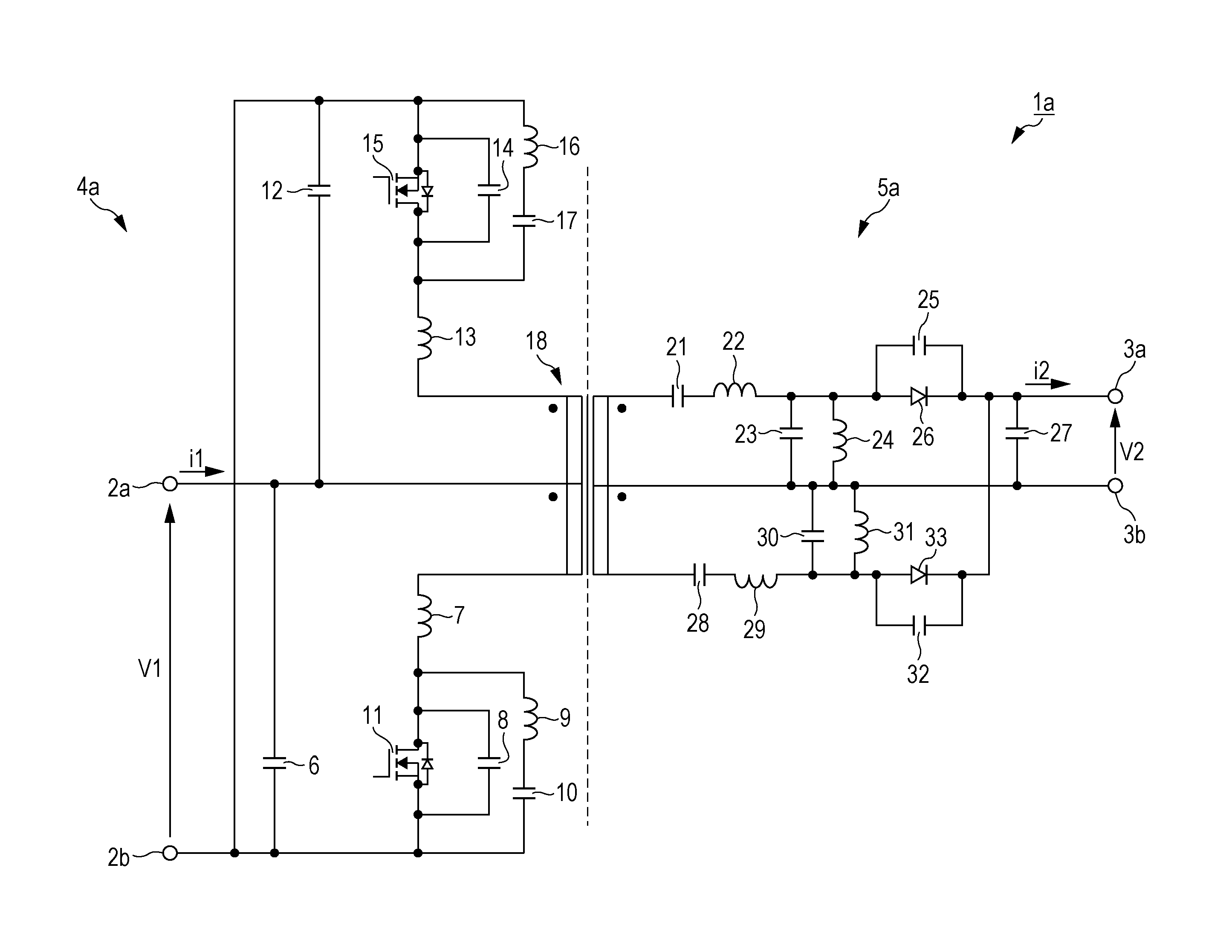
[0028]FIG. 1 is a circuit diagram illustrating a configuration of a resonant converter 1a (isolated resonant power supply device) according to a first embodiment of the present invention. The resonant converter 1a illustrated in FIG. 1 includes a pair of input terminals, namely, a first input terminal 2a and a second input terminal 2b (hereinafter also collectively referred to as an input terminal 2 unless specifically referred to otherwise), a pair of output terminals, namely, a first output terminal 3a and a second output terminal 3b (hereinafter also collectively referred to as an output terminal 3 unless specifically referred to otherwise), a resonant inverter 4a, and a resonant rectifier 5a. The resonant converter 1a converts an input voltage (DC voltage) V1 input to the input terminal 2 into an output voltage (DC voltage) V2 and outputs the output voltage V2 from the output terminal 3. In the resonant converter 1a, the input voltage V1 and an input current i1 are input to the ...

second embodiment

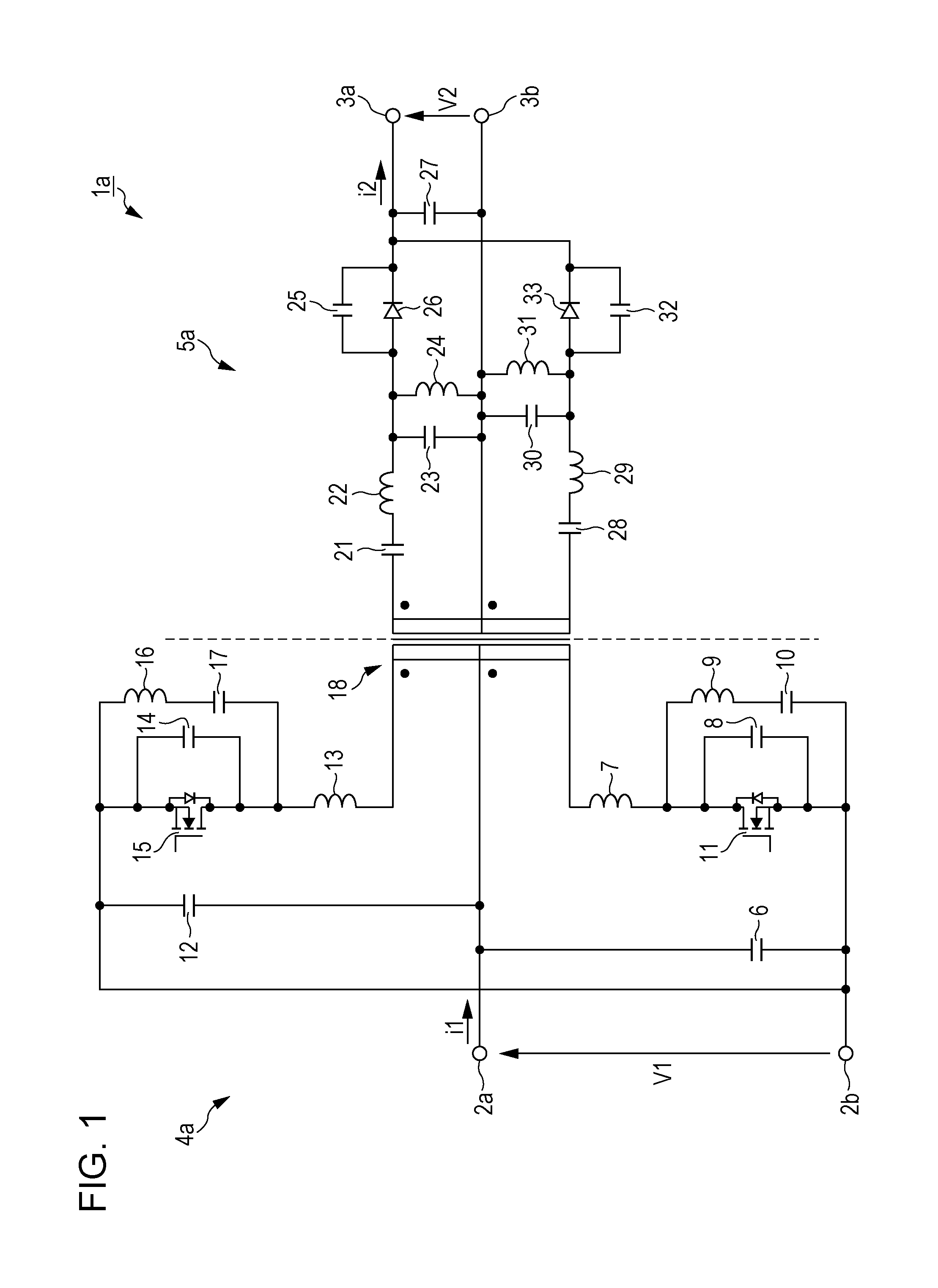
[0078]FIG. 2 illustrates a resonant converter according to a second embodiment of the present invention. The second embodiment is different from the first embodiment in that, in the resonant inverter 4a, the third or fourth resonant circuit, based on which the second resonance frequency F2 is determined as described in the first embodiment, is configured by using a fifth resonant circuit. Specifically, in the first embodiment, the third resonant circuit constituted by the fourth coil 9 and the fourth capacitor 10 and the fourth resonant circuit constituted by the fifth coil 16 and the fifth capacitor 17 constitute the resonant circuit based on which the second resonance frequency F2 is determined. However, in the second embodiment, the fifth resonant circuit is constituted by a third coil 39 and a third capacitor 40 (third capacitive element). One end of the third capacitor 40 is connected to the other end of the first coil 7 and to one end of the first winding of the transformer 18...

third embodiment

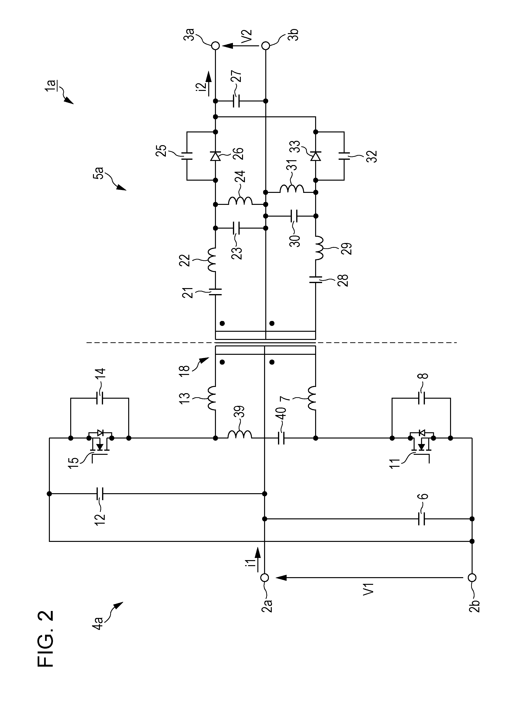
[0079]FIG. 3 illustrates a resonant converter circuit according to a third embodiment of the present invention. The third embodiment is different from the second embodiment in that the first coil 7 and the second coil 13 are replaced by the leakage inductance of the transformer 18. The configuration of the remaining portion is the same as that of the second embodiment. One end of the first capacitor 8 is connected to the drain of the first switch 11, to one end of the third capacitor 40, and to one end of the first winding of the transformer 18. The other end of the first capacitor 8 is connected to the source of the first switch 11, to the input terminal 2b, and so on. One end of the second capacitor 14 is connected to the drain of the second switch 15, to one end of the third coil 39, and to one end of the second winding of the transformer 18. The other end of the second capacitor 14 is connected to the source of the second switch 15, to the input terminal 2b, and so on. In other ...


PUM


Abstract

A resonant inverter includes an input terminal, a first switch, a second switch, a transformer, a first resonant circuit, and a second resonant circuit. To the input terminal, an input voltage is applied. The first switch and the second switch are alternately turned on and off. The transformer includes a first winding and a second winding on a primary side. The first resonant circuit includes a first capacitive element and a first coil. The second resonant circuit includes a second capacitive element and a second coil. The first switch, the first winding, and the first resonant circuit constitute a first inverter circuit. The second switch, the second winding, and the second resonant circuit constitute a second inverter circuit. The input terminal is connected between the first winding and the second winding.

Description

BACKGROUND OF THE INVENTION[0001]1. Field of the Invention[0002]The present invention relates to a resonant inverter and an isolated resonant power supply device in which the operating voltage of a switch included therein can be easily decreased.[0003]2. Description of the Related Art[0004]U.S. Pat. No. 7,889,519 discloses an isolated resonant converter in which an isolation transformer is placed on the resonant rectifier side in order to isolate and supply to a load the output of the resonant inverter (see FIG. 7). U.S. Pat. No. 7,924,580 discloses a non-isolated push-pull resonant inverter that includes two switches having phases which differ by 180 degrees and alternately turned on and off to supply power to a load (see FIG. 8). U.S. Pat. No. 7,889,519 and U.S. Pat. No. 7,924,580 disclose techniques in which the drain-source impedances of the switches are maximized at the drive frequency and at the frequency three times the drive frequency, and are minimized at the frequency abou...

Claims


Application Information

Patent Timeline
Patent Type & Authority Applications(United States)
IPC IPC(8): H02M3/335H02M7/537
CPCH02M3/33546H02M2007/4815H02M7/537H02M7/4815Y02B70/10H02M3/33576H02M3/33592
Inventor IMAI, KATSUNORI
Owner TDK CORPARATION
Why Eureka
Try Eureka