Method and apparatus for provisioning distribution channels in a communications network

a technology of communication network and distribution channel, applied in the field of communication, can solve the problems of affecting the performance of the network, and it takes several days, if not several weeks, to occur after, and achieve the effect of high data throughput rate and efficient utilization of network resources

Inactive Publication Date: 2006-02-21
LUCENT TECH INC +1
View PDF8 Cites 4 Cited by
  • Summary
  • Abstract
  • Description
  • Claims
  • Application Information

AI Technical Summary

Benefits of technology

[0011]If the RT cannot accommodate the user's provisioning selection, for example if there is insufficient feeder bandwidth to support the selected service, the RT notifies the user via the control channel and provisioning terminal so that the end user may select and initiate an alternative provisioning arrangement. By allowing a subscriber to dynamically provision distribution channels, the subscriber is able to efficiently util...

Problems solved by technology

Since this provisioning requires that the telephone company be involved, however, it ...

Method used


Image

  • Method and apparatus for provisioning distribution channels in a communications network
  • Method and apparatus for provisioning distribution channels in a communications network
  • Method and apparatus for provisioning distribution channels in a communications network

Examples


Embodiment Construction

[0017]The present invention is a method and an apparatus which enables an end user to provision distribution channels in a communications network. According to an embodiment of the present invention, an end user allocates digital distribution channels of a communications network with includes digital carrier loop (DLC) technology.

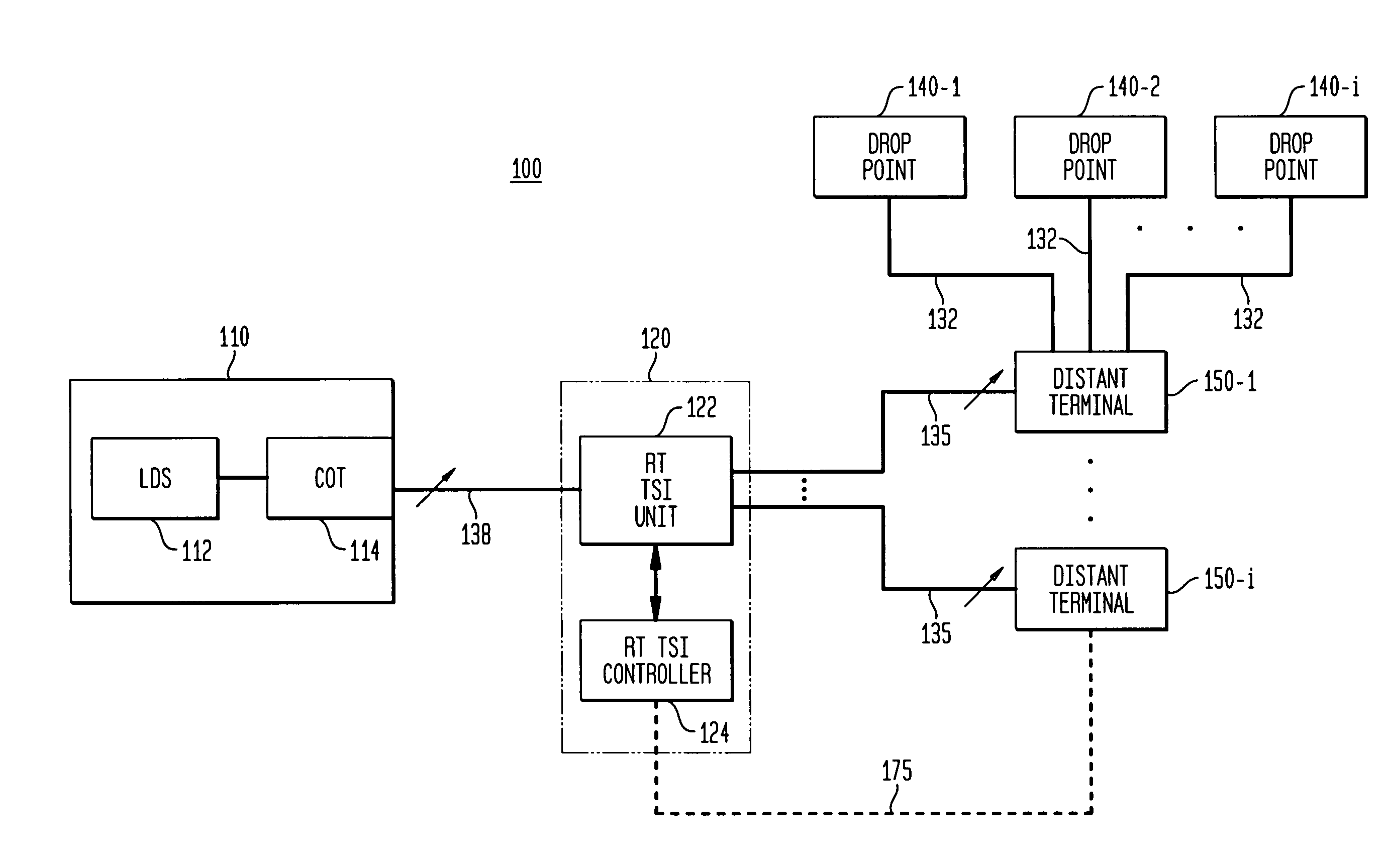
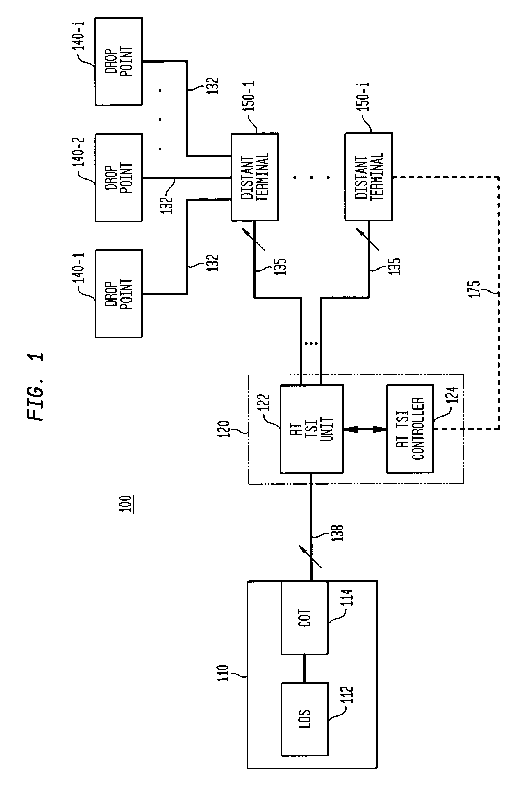
[0018]FIG. 1 illustrates an exemplary network configuration which is suitable for implementing embodiments of the present invention. As shown in FIG. 1, a communications network 100 includes a central office (CO) 110, a remote terminal (RT) 120, a plurality of distant terminals (DTs) 150-1, . . . , 150-i, and a number of subscriber drop points 140-1, . . . , 140-i fed off an associated DT 150-1. The subscriber drop points 140-1 . . . 140-i are connected to their associated DT 150-1 via narrow-band analog lines 132, such as copper wire pairs. Each of the DTs 150-1, . . . , 150-i is connected to the RT 120 via a high-bandwidth digital transmission line (or a ...


PUM


Abstract

A method and an apparatus for user-based provisioning of distribution channels in a communications network allows an end user to select and initiate digital distribution channel allocation to accommodate their needs instead of submitting a service order to the telephone company each time a change in channel allocation is desired. In one implementation, a user-accessed provisioning terminal at a Distant Terminal (DT) receives a subscriber's distribution channel allocation selection after the user is authorized. The user's allocation selection is transmitted to a Remote terminal (RT) via a control channel, such as the Facility Data Line of an ESF-type T1 line or a dedicated data link that directly connects the DT and an RT. When the RT receives a provisioning message from a DT, the RT confirms that the provisioning selection is acceptable and automatically rearranges its time-slot interchange (TSI) connections according to the provisioning change initiated by the user. The RT sends an acknowledgement to the user-accessed provisioning terminal at the DT, which rearranges the TSI connections at the DT in accordance with the user's provisioning selection. If the RT cannot accommodate the user's provisioning selection, for example if there is insufficient feeder bandwidth to support the selected service, the RT notifies the user via the control channel and provisioning terminal so that the end user may select and initiate an alternative provisioning arrangement.

Description

BACKGROUND OF THE INVENTION[0001]1. Field of the Invention[0002]The present invention relates to the field of communications, and more particularly to an apparatus and a method for provisioning distribution channels in a communications network.[0003]2. Description of Related Art[0004]Using digital loop carrier (DLC) technology, telephone companies are now able to efficiently serve large numbers of subscribers and expand the capacity of their networks. In contrast to a conventional local loop, i.e. a voice frequency (VF) channel formed by running copper wire pairs between each subscriber and a central office, a DLC system connects a number of subscribers to a central office through high-bandwidth digital transmission lines, such as fiber-optic or T1 lines. Next Generation Digital Carrier Loop (NGDLC) systems include time slot interchange (TSI) capability, which allows the service provider to establish and change connections between subscribers and digital distribution channels.[0005]...

Claims


Application Information

Patent Timeline
IPC IPC(8): H04J3/16H04J3/22
CPCH04J3/1682
Inventor BOLLING, ANTHONY C.
Owner LUCENT TECH INC
Why Eureka
Try Eureka