Image recording device and an image recording system

a recording device and image technology, applied in the direction of optical radiation measurement, instruments, inking apparatus, etc., can solve the problems of uneven intervals of beam spots, low positioning accuracy of beam spots in subsidiary scanning directions, and troublesome scanning lines, etc., to achieve high-quality images

Inactive Publication Date: 2006-02-21
RICOH PRINTING SYST
View PDF18 Cites 35 Cited by
  • Summary
  • Abstract
  • Description
  • Claims
  • Application Information

AI Technical Summary

Benefits of technology

[0032]The beam signal controlling unit provided as described above can correct positional deviatio

Problems solved by technology

One problem is that the positional accuracy of beam spots in the subsidiary scanning direction is low.
This may be mainly caused by the following:(1) Influence due to the positional accuracy of the multi-beam structure;(2) Influence due to the horizontal magnification error in the optical system;(3)

Method used


Image

  • Image recording device and an image recording system
  • Image recording device and an image recording system
  • Image recording device and an image recording system

Examples


Embodiment Construction

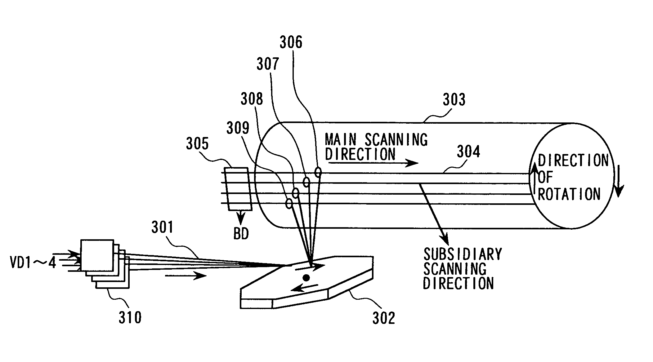
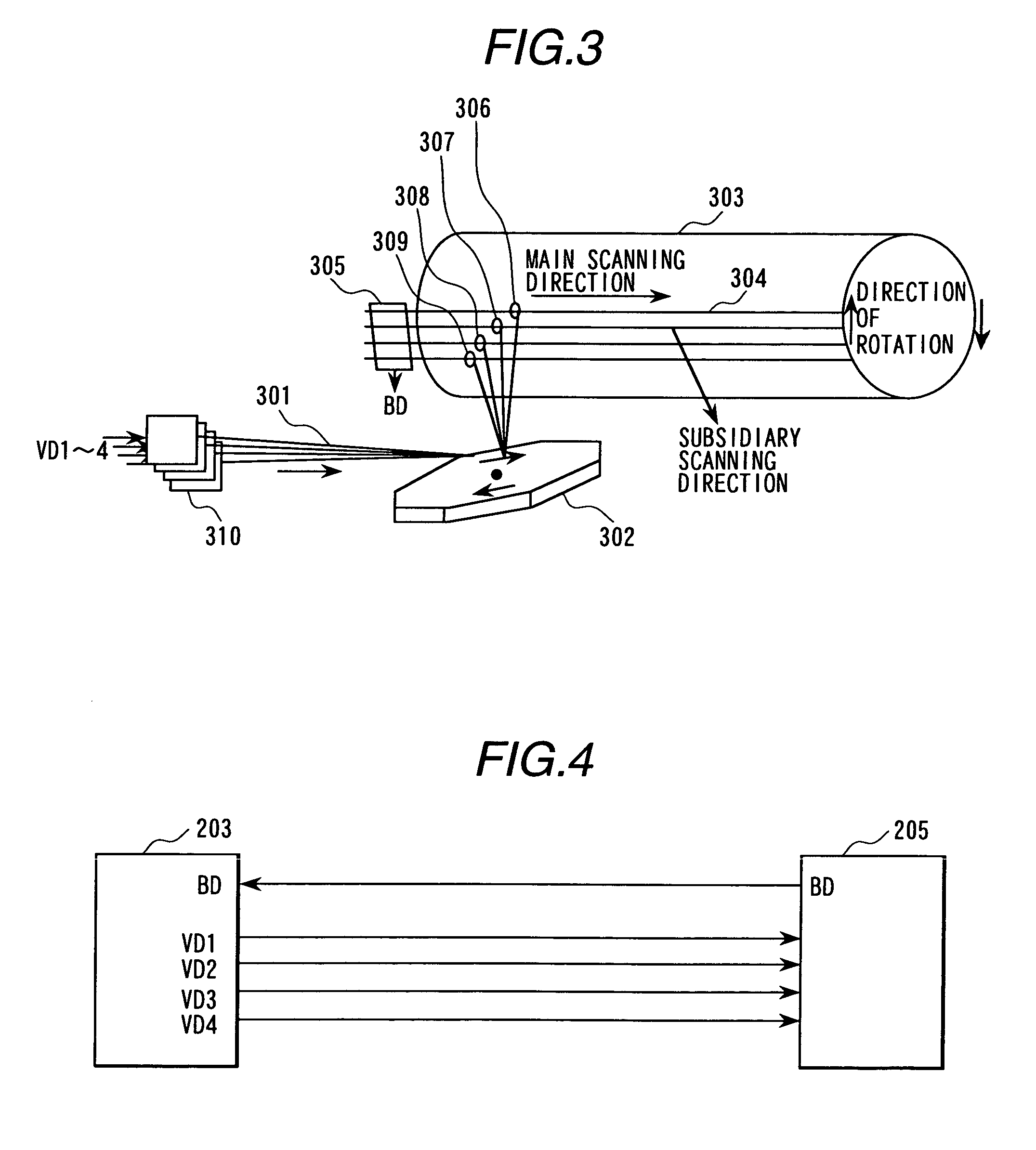
[0124]Referring to FIG. 1 to FIG. 18 and FIG. 22 to FIG. 28, preferred embodiments of the present invention will be explained.

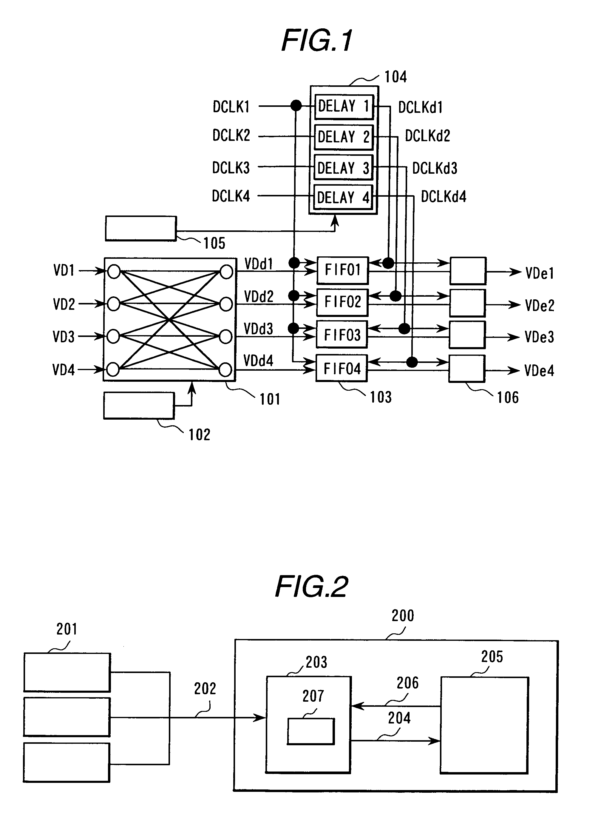
[0125]In FIG. 2, there is shown an operating environment of a general image recording device. The user creates page description data 202 which represents pages to be recorded using a computer 201 and the like. When recording starts, the page description data 202 is sent to a printer controller 203 of an image recording device 200 through a network and the like. The image recording device 200 mainly consists of a printer controller 203 and an engine 205. The printer controller 203 expands page description data 202 page by page as image data 207 on a built-in bit-map memory.

[0126]This embodiment assumes that image data 207 is printed on a monochromatic binary laser printer and one piece of binary data is related to one bit of one pixel. After expansion of image data 207 is completed, the printer controller 203 starts the engine 205 of the image recording device...


PUM


Abstract

A multi-beam image recording device is capable of recording high-quality high-resolution images without positional errors by exposing test patterns for measuring positional errors of beam spots of each laser beam in main and subsidiary scanning directions, calculating the positional errors of beam spots using a correcting device, controlling the quantity of exposure according to the result of calculation, and thus correcting the positional errors in main and subsidiary scanning directions.

Description

BACKGROUND OF THE INVENTION[0001]The present invention relates to an image recording device and an image recording system having a plurality of laser beams (multi-laser beam).[0002]An image-recording device using a laser beam has been widely used because it runs faster with a higher resolution than image-recording devices based on other technologies.[0003]A conventional printer using one laser beam (laser printer) is disclosed in Japanese patent application laid-open publication No. Hei 8-310057 (1996). The printer utilizes features of continuously modulating laser intensities in the main scanning direction and controlling the quantity of attached toner by controlling laser intensities for high-resolution printing. These features eliminate and reduce the irregularities in slanted outlines of characters and images, which makes the printout images and characters smooth.[0004]To run the laser beam printer faster, it is required to make the laser beam (the light beam of a laser) scan at...

Claims


Application Information

Patent Timeline
IPC IPC(8): G03G15/00B41J2/47
CPCB41J2/473
Inventor KOBAYASHI, SHINYASATOH, KUNIOEDO, SUSUMUMARUO, SEIJIKUMASAKA, TAKAOONOSE, ATSUSHI
Owner RICOH PRINTING SYST
Why Eureka
Try Eureka