Rotary cutting saw with improved heat dissipation performance

a technology of heat dissipation performance and cutting saw, which is applied in the direction of gear teeth, gear teeth, gear manufacturing apparatus, etc., can solve the problems of ineffective prevention of burning, increased risk of cutting chips, etc., to reduce the amount of axial runout of the cutting saw as measured, increase the diameter of the cutting saw, and reduce the effect of the load

Active Publication Date: 2006-02-28
NORITAKE SUPER ABRASIVE CO LTD +1
View PDF13 Cites 8 Cited by
  • Summary
  • Abstract
  • Description
  • Claims
  • Application Information

AI Technical Summary

Benefits of technology

[0019]In the rotary cutting saw defined in any one of the first through tenth aspects of the invention, owing to the presence of the clearance whose size corresponds to 5–150% of the size of the axial-runout restraining member, it is possible to obtain an improved heat dissipation performance and prevent burning in the abrasive segments even in a dry-cutting operation, ie., a cutting operation without application of a cutting fluid to the cutting saw. Further, owing to the provision of the axially-runout restraining members, it is possible to restrain the axial runout of the cutting saw, i.e., an axial motion of each abrasive segment fixed to the outer circumferential surface of the base disk, since the axially-runout restraining members are brought into contact with a work material when the cutting saw suffers from its axial runout within a slot which is being currently cut or formed by the cutting saw. It is noted that the rotary cutting saw according to the present invention may be referred also to a cutting blade, a rotary blade, a cutting grindstone or a grinding wheel.
[0020]In the rotary cutting saw of the present invention, the ratio of the size of the clearance with respect to the size of the axial-runout restraining member is not lower than 5% and is not higher than 150%, so that the cutting saw is given a sufficiently high degree of heat dissipating capacity and a sufficiently high degree of blade tension. If the ratio is lower than 5%, the rotary cutting saw cannot be given the sufficiently high degree of heat dissipating capacity. If the ratio is higher than 150%, on the other hand, the rotary cutting saw cannot be given the sufficiently high degree of blade tension. It is noted that the ratio is preferably 50–100%, so that the rotary cutting saw is given a higher degree of heat dissipating capacity and a higher degree of blade tension. It is noted that the term “blade tension” used in the present specification should be interpreted to mean a tension which tends to stretch the base disk in its radially outward direction and which is given, for example, by hammering a peripheral portion of the base disk in a process of manufacturing the cutting saw. The base disk is thus pretensioned to have an increased rigidity, which prevents deformation of the base disk during a cutting operation as a practical use of the cutting saw.
[0022]The amount of the axial runout of the cutting saw as measured at each abrasive segment is increased with increase of the diameter of the cutting saw. However, the rotary cutting saw defined in the seventh aspect of the invention, in which the axial-runout restraining members are received in the radially outside and inside apertures, can be advantageously made large in size. Since the axial-runout of the cutting saw is restrained by the axial-runout restraining members received in the radially outside apertures and those received in the radially inside apertures, namely, since the axial-runout of the cutting saw is restrained in steps, it is possible to reduce a load exerted to each one of the restraining members.
[0023]Each of the axial-runout restraining members tends to be worn more at its radially outer portion than at the other portion, since the restraining member tends to be brought into contact more easily at its radially outer portion than the other portion, with the side surfaces of the slot formed in the work material. In the rotary cutting saw defined in the eighth aspect of the invention, in which the width of each axial-runout restraining member is reduced as viewed in the direction away from the outer periphery of the base disk toward the axis of the base disk, namely, is increased in a direction away from the axis to the outer periphery, such a local wear of each axial-runout restraining member at its radially outer portion can be restrained.
[0024]In the rotary cutting saw defined in each of the ninth and tenth aspects of the invention, each axial-runout restraining members is welded or otherwise fixed at its front side surface to the inner circumferential surface of the corresponding aperture, so that the clearance defined between the periphery of each aperture and the corresponding axial-runout restraining member is located on a rear side of the restraining member as viewed in the rotating direction. This arrangement is effective to prevent the clearance from being clogged with chips and accordingly avoid reduction in the heat dissipation performance.

Problems solved by technology

In a dry-cutting operation in compared with a wet-cutting operation, the cutting saw is less cooled so that the cutting chips are more likely to be burned due to generation of heat at their side surfaces, which are rubbed against a cut surface of the pavement since the cutting saw tends to suffer from an axial runout or a side-wall runout due to cutting resistance exerted to the cutting chips.
Further, if each cutting chip is worn at its side surfaces to such an extent that causes side or axially opposite end surfaces of the base disk to be brought into contact with the cut surface, the base disk is heated whereby its blade tension is undesirably reduced.
This arrangement makes it possible to prevent wear of the base disk, but is not effective to prevent burning in the major cutting chips, which is problematic particularly in a dry-cutting operation.
Further, since the auxiliary cutting chips provided on the axially opposite end surfaces of the base disk cut the side surfaces of the cut slot, namely, the width of the cut slot is increased by the auxiliary cutting chips, the cutting saw becomes more movable within the cut slot in its axial direction, thereby making it impossible to restrain the axial runout of the cutting saw.
In a dry-cutting operation, the axial runout of the cutting saw leads to reduction in the cutting performance due to heat generation and wear of the cutting chips.

Method used


Image

  • Rotary cutting saw with improved heat dissipation performance
  • Rotary cutting saw with improved heat dissipation performance
  • Rotary cutting saw with improved heat dissipation performance

Examples


first embodiment

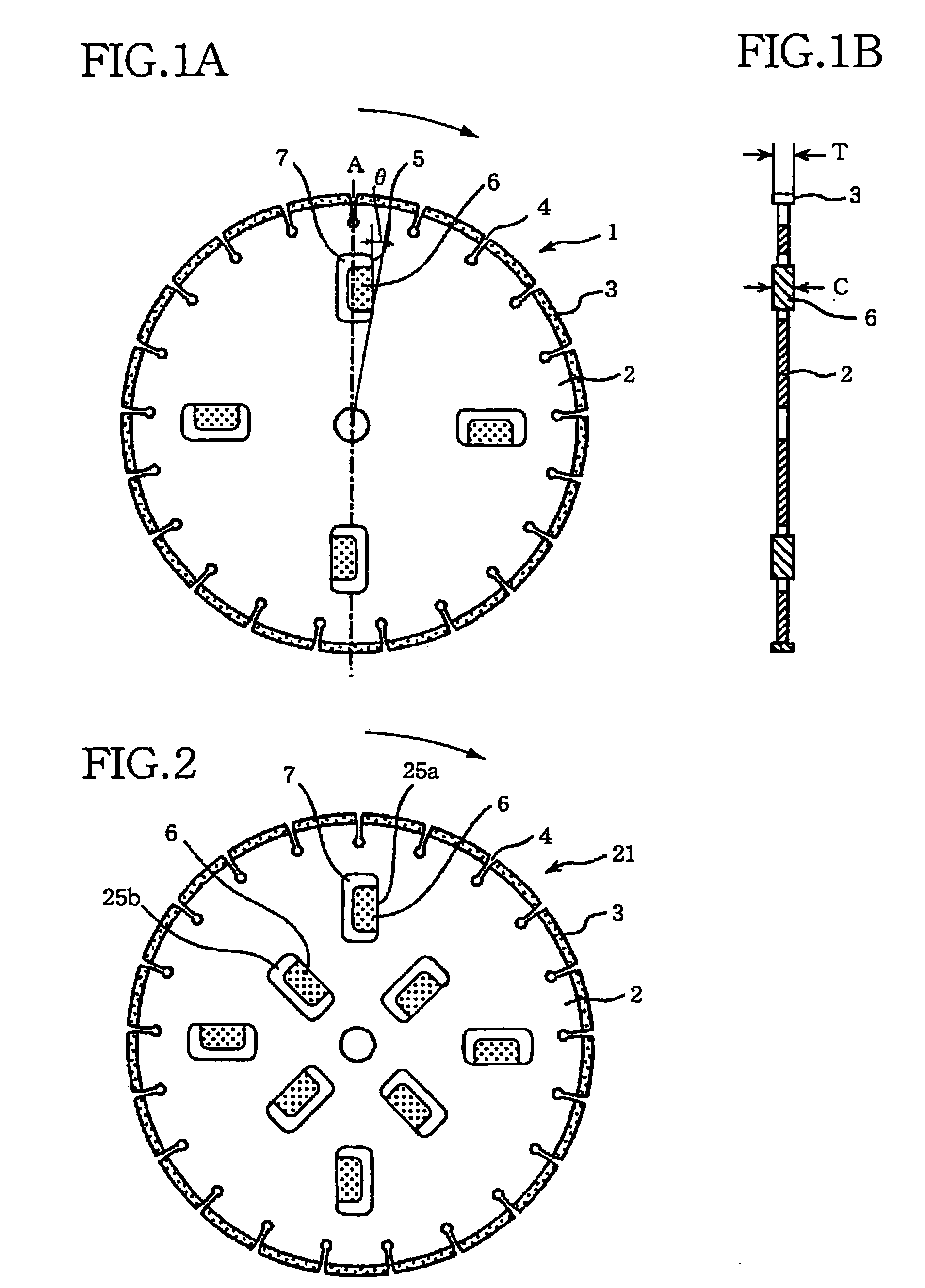
[0031]Referring first to FIGS. 1A and 1B, there will be described a rotary cutting saw 1 constructed according to the invention. This rotary cutting saw 1 includes a circle-shaped base disk 2, a plurality of cutting chips 3 as abrasive segments, and a plurality of hard chips 6 as axial-runout restraining members or side-wall runout restraining members. The cutting chips 3 are fixed to an outer circumferential surface of the base disk 2 such that the cutting chips 3 are equally spaced apart from each other in a circumferential direction of the base disk 2. The base disk 2 has a plurality of chip-evacuation slits 4 formed between the cutting chips 3, so as to extend inwardly in a radial direction of the base disk 2 from the outer circumferential surface and also in an axial direction oft the base disk 2 over an entire thickness or axial length of the base disk 2. The base disk 2 has also a plurality of apertures 5 formed therethrough and opening in axially opposite end surfaces thereo...

second embodiment

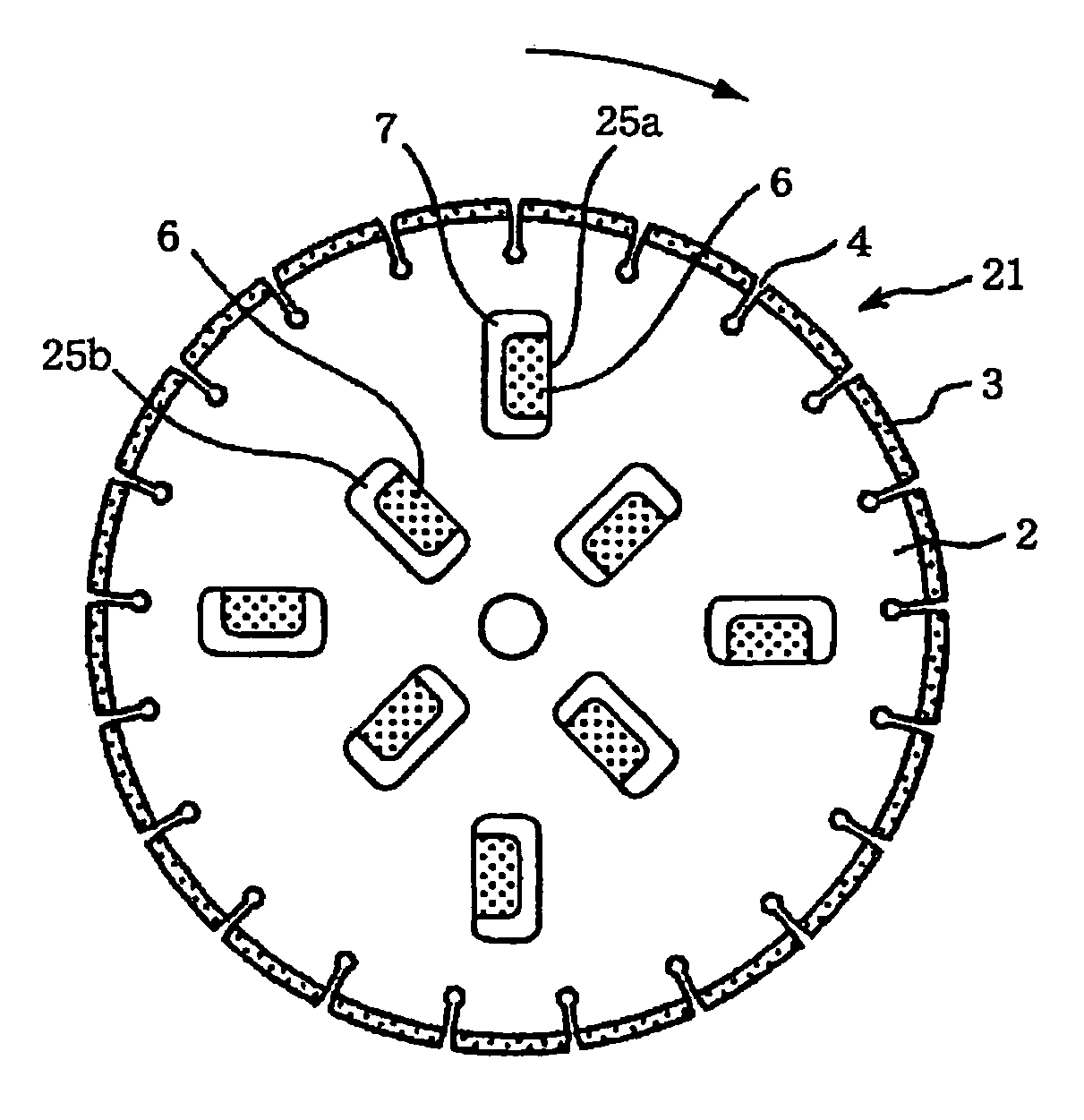
[0036]FIG. 2 shows another rotary cutting saw 21, which is constructed according to the invention. Like the above-described rotary cutting saw 1 of FIGS. 1A and 1B, this rotary cutting saw 21 has the base disk 2, the plurality of cutting chips 3 attached to the outer circumferential surface of the base disk 2, and the chip-evacuation slits 4 formed between the cutting chips 3. However, this cutting saw 21 is different from the above-described cutting saw 1 in that its base disk 2 has a plurality of radially outside and inside apertures 25a, 25b formed therethrough such that the radially inside apertures 25b are located radially inwardly of the radially outside apertures 25a. It is preferable that the radially outside apertures 25a are equally spaced apart from each other in the circumferential direction of the base disk 2, and that the radially inside apertures 25b are equally spaced apart from each other in the circumferential direction, too. Like each of the apertures 5 of the cut...

third embodiment

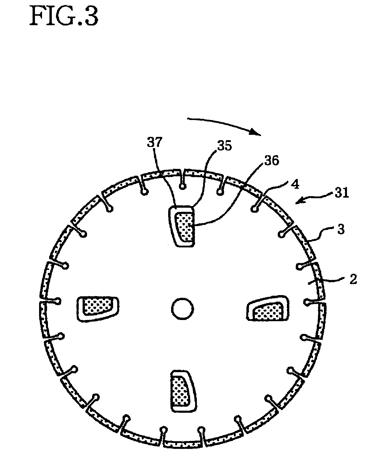
[0037]FIG. 3 shows still another rotary cutting saw 31, which is constructed according to the invention. Like the above-described rotary cutting saw 1 of FIGS. 1A and 1B, this rotary cutting saw 31 has the base disk 2, the plurality of cutting chips 3 attached to the outer circumferential surface of the base disk 2, and the chip-evacuation slits 4 formed between the cutting chips 3. However, this cutting saw 31 is different from the above-described cutting saw 1 in that its base disk 2 has, in place of the above-described apertures 5, a plurality of apertures 35 has a width which is gradually changed as viewed in the radial direction of the base disk 2. Specifically described, each of the apertures 35 is provided by an elongated hole which is elongated in the radial direction of the base disk 2, and has a width (as measured in the circumferential direction of the base disk 2) which is reduced as viewed in a direction away from the outer periphery of the base disk 2 toward the axis o...


PUM

PropertyMeasurementUnit
distanceaaaaaaaaaa
diameteraaaaaaaaaa
sizeaaaaaaaaaa

Abstract

A rotary cutting saw including: (a) a base disk which has a plurality of apertures formed therethrough and opening in axially opposite end surfaces thereof; (b) a plurality of abrasive segments which are fixed to an outer circumferential surface of the base disk; and (c) a plurality of axial-runout restraining members which are received in the apertures. Each of the axial-runout restraining members has a size which is smaller than a size of each of the apertures, such that a clearance is defined between the periphery of each of the apertures and a corresponding one of the axial-runout restraining members which is received in the each of the apertures. A ratio of a size of the clearance to the size of each of the axial-runout restraining members is 5–150%.

Description

BACKGROUND OF THE INVENTION[0001]1. Field of the Invention[0002]The present invention relates in general to a rotary cutting saw, and more particularly to such a rotary cutting saw of so-called “dry-cutting type” which is used for cutting or parting a pavement surface.[0003]2. Discussion of the Related Art[0004]In a road construction or restoration, a pavement surface is cut or parted by using commonly a rotary cutting saw including a circle-shaped base disk and diamond cutting chips which are attached to an outer circumferential surface of the base disk. In a dry-cutting operation in compared with a wet-cutting operation, the cutting saw is less cooled so that the cutting chips are more likely to be burned due to generation of heat at their side surfaces, which are rubbed against a cut surface of the pavement since the cutting saw tends to suffer from an axial runout or a side-wall runout due to cutting resistance exerted to the cutting chips. Further, if each cutting chip is worn ...

Claims


Application Information

Patent Timeline
Patent Type & Authority Patents(United States)
IPC IPC(8): B28D1/04E01C23/09B23D61/02B24D5/00B24D5/06B24D5/12B28D1/12B28D1/24
CPCB28D1/121B23D61/026
Inventor SAKITA, KAZUYUKINIIZAWA, YOJI
Owner NORITAKE SUPER ABRASIVE CO LTD
Why Eureka
Try Eureka