Fluid control apparatus

a technology of control apparatus and fluid, which is applied in mechanical apparatus, multiple way valves, transportation and packaging, etc., can solve the problems of necessitating time and labor for interconnection lines, and achieve the effect of increasing the number of components and being more amenabl

Inactive Publication Date: 2006-02-28
FUJIKIN INC
View PDF4 Cites 20 Cited by
  • Summary
  • Abstract
  • Description
  • Claims
  • Application Information

AI Technical Summary

Benefits of technology

[0014]An object of the present invention is to provide an integrated fluid control apparatus which has line interconnecting means for interconnecting channels of lines and which is reduced in the increase in the number of components (kinds of channel blocks, i.e., of block couplings) in eliminating welded portions from the line interconnecting means, the apparatus thus being made more amenable to the addition or modification of lines.
[0018]With the fluid control apparatus of the present invention, at least one of line interconnecting means comprises a lateral projection formed on one of the front and rear block couplings of the first line, a recessed portion formed in the block coupling of the second line for the lateral projection to fit in, a coupling branch channel formed in the block coupling provided with the lateral projection and having an end opening in a coupling body upper surface and another end opening in an upper surface of the lateral projection, a first valve body branch channel formed in a body of the shut-off valve of the first line for always causing a main channel in the valve body to communicate with the coupling body upper surface opening of the coupling branch channel, and a second valve body branch channel formed in a body of the shut-off valve of the second line for always causing a main channel in the valve body to communicate with the lateral projection upper surface opening of the coupling branch channel. Accordingly, the line interconnecting means can be fabricated without welding, and block couplings having the lateral projection and the recessed portion can be made to have the same contour as other block couplings when the lateral projection is fitted into the recessed portion of like coupling adjacent thereto. This reduces an increase in the number of components, ensures flexible design and results in improved amenability to maintenance.
[0019]When an additional line is to be provided, a space having a width slightly larger than the width of one line (larger by an amount corresponding to the lateral projection) is prepared between adjacent lines to provide a new line (having incorporated therein components other than shut-off valves) in the space. The lateral projection of the block coupling of the first line is then fitted into the recessed portion of block coupling of the second line, the lines are positioned closer to each other and fixed in place, and shut-off valves are finally incorporated into the new line. A similar procedure is performed when lines are to be modified. In this way, lines can be additionally provided or modified easily.
[0024]Preferably, the line interconnecting means comprises a plurality of two-way connecting block couplings one of which is positioned at one end of the line interconnecting means and has no lateral projection and no branch channel, and the others of which each have the lateral projection and the branch channel. The two-way connecting block coupling positioned at one end (interfering with other line) of the line interconnecting means has no lateral projection and no branch channel, whereby the coupling can be made free of interference with other line. The number of block couplings can be reduced by eliminating one-way connecting block couplings which are provided with a lateral projection only.

Problems solved by technology

However, since the line interconnecting means comprises couplings which are welded to a pipe for connection, the apparatus has the problem of necessitating time and labor for interconnecting the lines and disconnecting the lines from one another when lines are to be added or the arrangement of lines is to be altered.

Method used


Image

  • Fluid control apparatus
  • Fluid control apparatus
  • Fluid control apparatus

Examples


Embodiment Construction

[0037]An embodiment of the present invention will be described below with reference to the drawings.

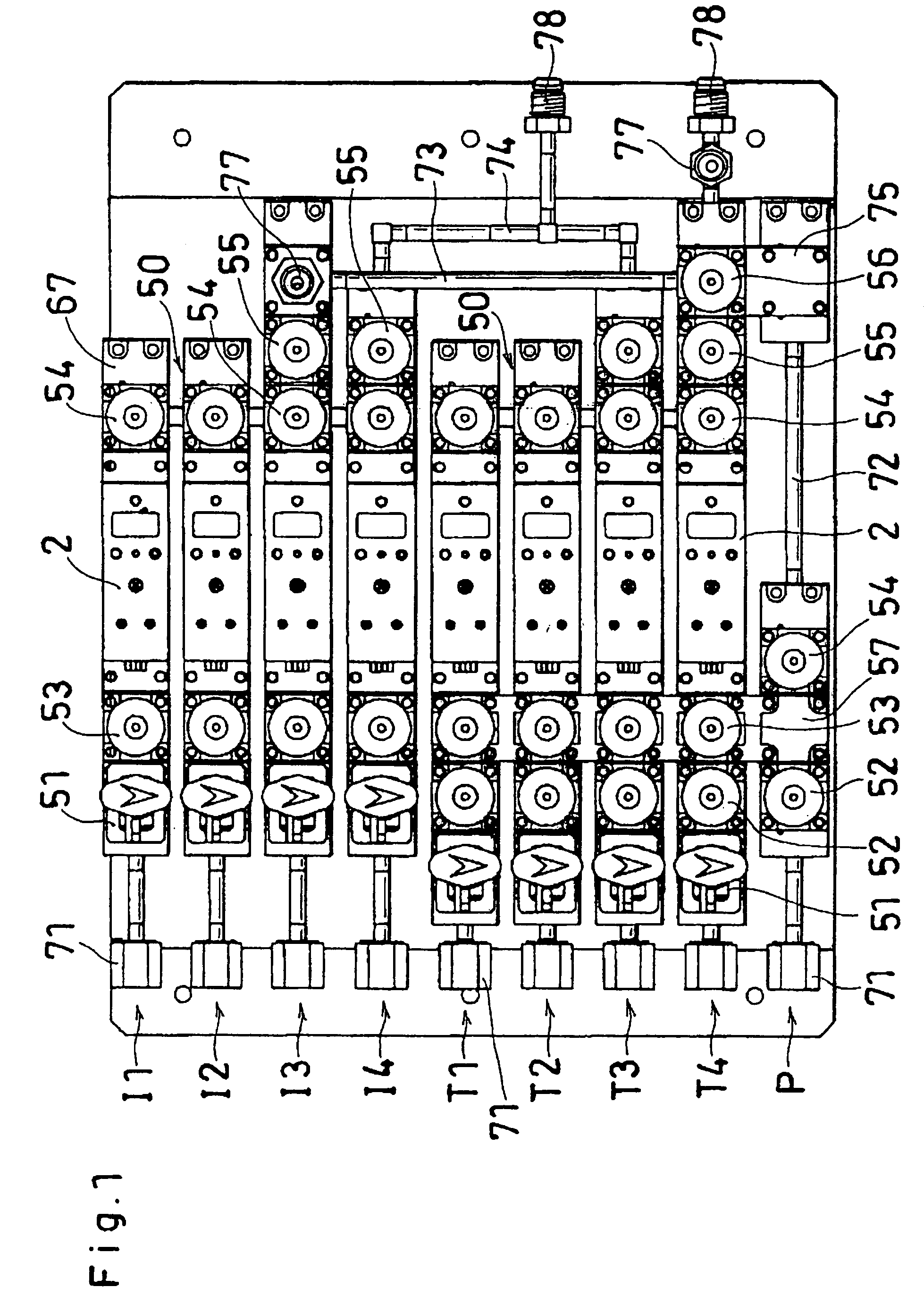
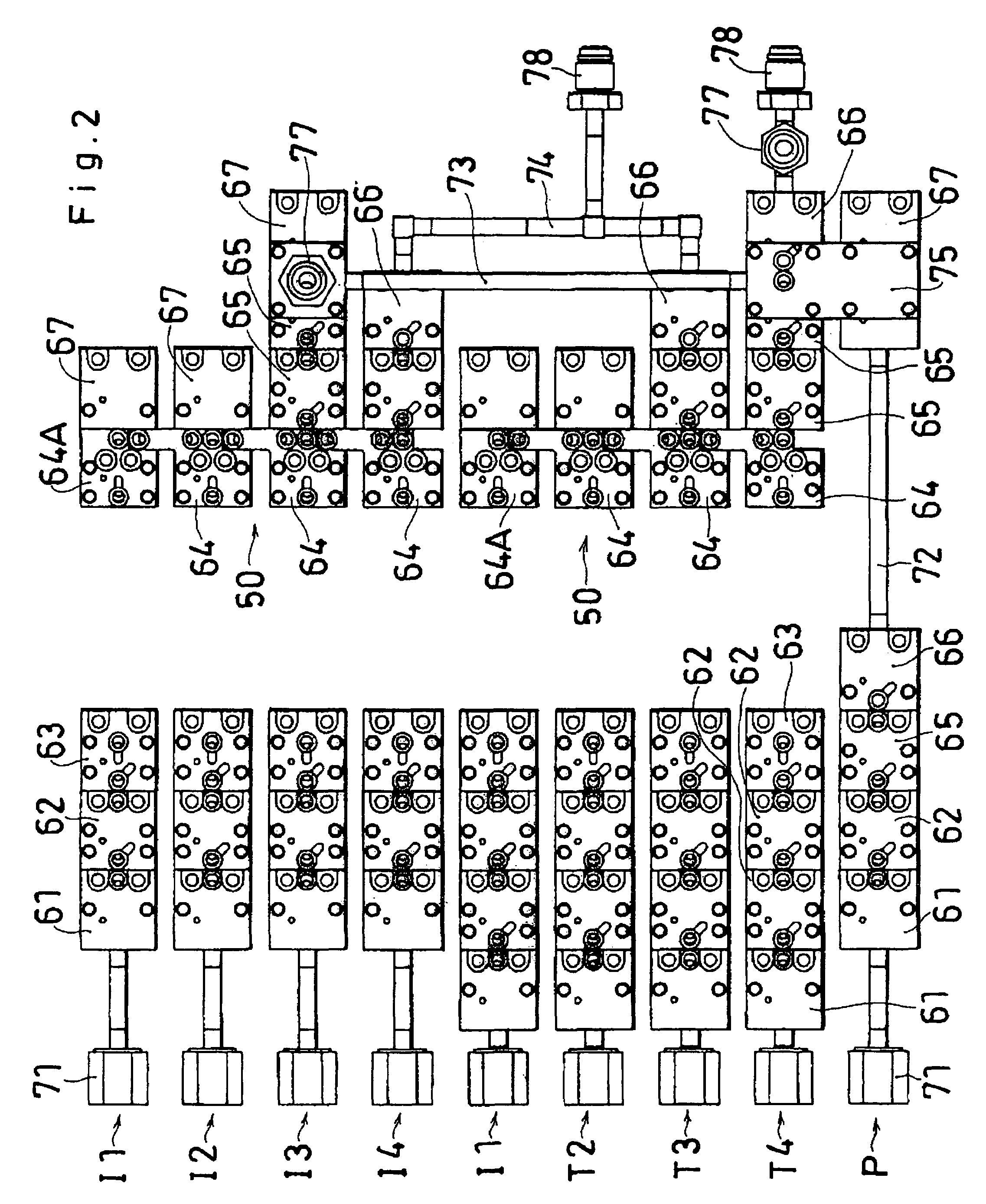
[0038]FIGS. 1 and 2 show the overall construction of a fluid control apparatus of the invention.

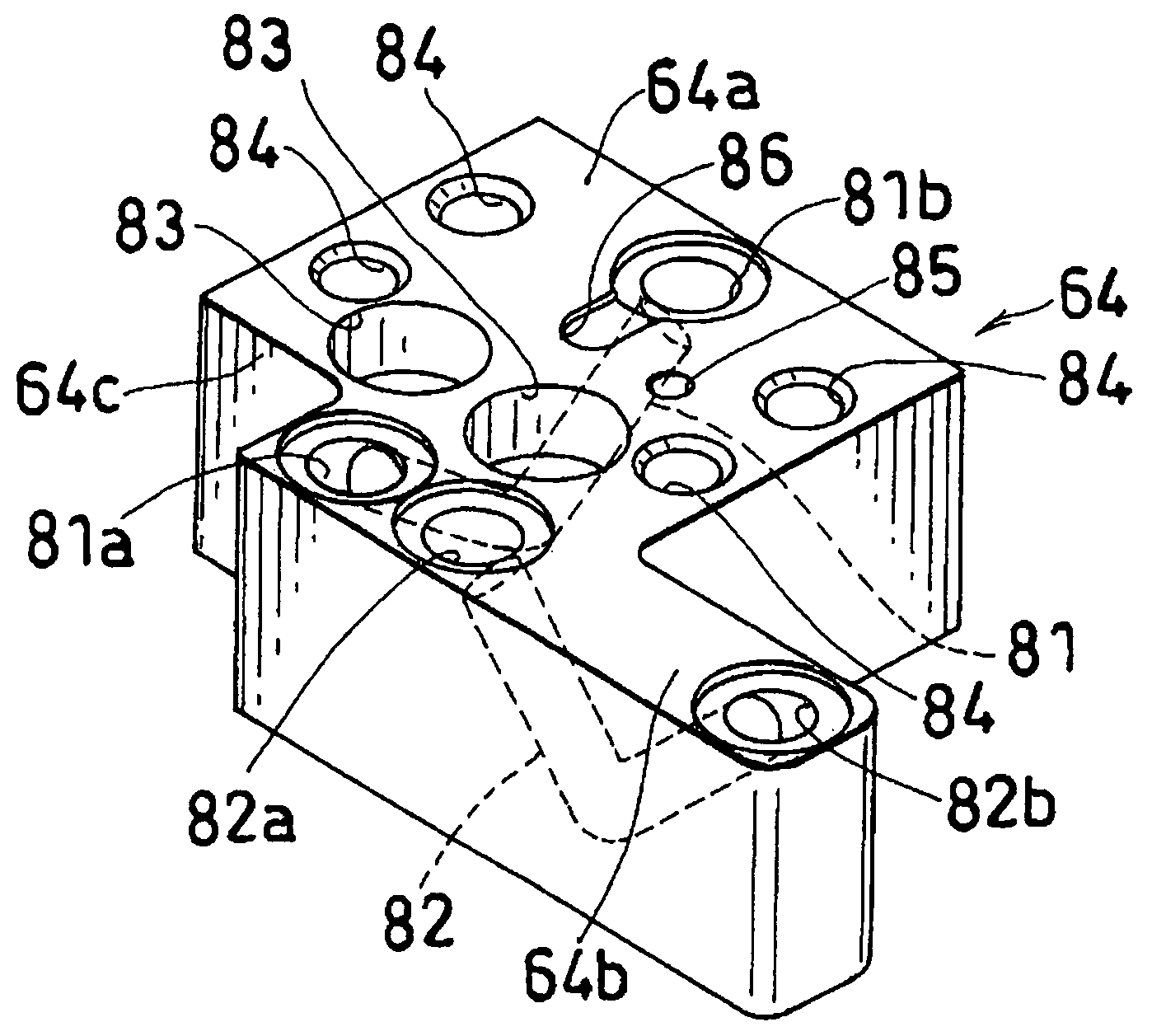
[0039]The fluid control apparatus has a plurality of lines I1, I2, I3, I4, T1, T2, T3, T4, P including inert gas lines I1, I2, I3, I4, treatment gas lines T1, T2, T3, T4 and one purge gas line P. Each of the lines I1, I2, I3, I4, T1, T2, T3, T4, P comprises a lower layer (FIG. 2) having a plurality of block couplings 61, 62, 63, 64, 65, 66 arranged forward or rearward, and an upper layer (FIG. 1) having a plurality of fluid control devices 2, 51, 52, 53, 54, 55, 56 arranged forward or rearward.

[0040]FIG. 3 shows the construction of the line T4 as an example of construction of one line. The line T4 comprises a mass flow controller 2 constituting the upper layer, four inlet-side block couplings 61, 62, 62, 63 arranged at the inlet side of the controller and constituting the lower layer, three...


PUM


Abstract

Line interconnecting means interconnecting two lines adjacent to each other laterally thereof comprises a lateral projection 64b formed on a two-way connecting block coupling 64 of the first of the lines, a recessed portion 54c formed in a two-way connecting block coupling 64 of the second of the lines for the lateral projection 64b to fit in, a coupling branch channel 82 formed in the block coupling 64 provided with the lateral projection, a first valve body branch channel 90A formed in the body 54a of a shut-off valve 54 of the first line for always causing a main channel 89 in the valve body to communicate with the coupling body upper surface opening 82a of the coupling branch channel 82, and a second valve body branch channel 90B formed in the body 54a of a shut-off valve 54 of the second line for always causing a main channel 89 in the valve body to communicate with a lateral projection upper surface opening of the coupling branch channel 82.

Description

BACKGROUND OF THE INVENTION[0001]The present invention relates to fluid control apparatus for use in semiconductor manufacturing equipment, and more particularly to integrated fluid control apparatus which are so assembled that fluid control devices can be individually removed upward for maintenance and inspection.[0002]As to the terms “front,”“rear,”“upper” and “lower” used herein, the right-hand side of FIGS. 1 to 3 is referred to as “front,” the left-hand side thereof as “rear,” and the upper and lower sides of FIG. 3 are referred to as “upper” and “lower,” respectively, and the terms “left” and “right” are used for the apparatus or the component thereof as it is seen from behind toward the front. The terms front, rear, upper and lower are used for the sake of convenience; the apparatus may be used with its front and rear portions positioned in opposite relation, or with the upper and lower sides thereof positioned as the left and right sides.[0003]Fluid control apparatus for sem...

Claims


Application Information

Patent Timeline
Patent Type & Authority Patents(United States)
IPC IPC(8): F16K11/10
CPCF17D1/04Y10T137/87885
Inventor FUNES, WARNER F.OCHS, GREGORY W.ITOI, SHIGERU
Owner FUJIKIN INC
Why Eureka
Try Eureka