Lift and twist control using trailing edge control surfaces on supersonic laminar flow wings

a supersonic laminar flow and control surface technology, applied in the direction of wing shapes, transportation and packaging, efficient propulsion technologies, etc., can solve the problems of creating undesirable control characteristics, and reducing the maximum achievable wing lift, etc., to achieve low torsional stiffness and low sweep angularity

Active Publication Date: 2006-02-28
AERION INTPROP MANAGEMENT CORP
View PDF14 Cites 18 Cited by
  • Summary
  • Abstract
  • Description
  • Claims
  • Application Information

AI Technical Summary

Benefits of technology

[0002]Supersonic aircraft designed with thin, low sweep wings designed for extensive natural laminar flow tend to have low torsional stiffness. In subsonic flight the center of pressure is typically ahead of the wing torsional elastic center creating a moment twisting the wingtip to higher angle of attack—“wash-in”. At supersonic conditions the center of pressure is much closer to the wing elastic center, reducing or reversing the “wash-in”. A wing with a twist distribution optimized for supersonic cruise will thus have significant “wash-in” at subsonic speeds. This induces pre-mature tip stall, reducing the maximum achievable wing lift and creating undesirable control characteristics, at stall.
[0005]The above described problems and difficulties can be mitigated by deflection of trailing edge control surfaces on such supersonic aircraft. A trailing edge flap has the effect of moving the center of pressure aft, thus reducing the wash-in effect when deployed at subsonic speeds. The trailing edge flaps also introduce aft camber which reduces subsonic leading edge vortex drag and compressibility drag rise.
[0013]As will be seen, the wings may typically have low sweep angularity relative to the fuselage to provide substantial laminar airflow, the wings further characterized as having relatively low torsional stiffness.
[0017]Another object is to provide flaps that are characterized by camber acting to reduce subsonic wing leading edge vortex drag, and compressibility drag increase.

Problems solved by technology

This induces pre-mature tip stall, reducing the maximum achievable wing lift and creating undesirable control characteristics, at stall.
Thin supersonic airfoil sections with low camber also have significant drag penalties at subsonic conditions due leading edge vortex drag.
This penalty increases at high subsonic Mach number cruise conditions with a pronounced drag rise.

Method used


Image

  • Lift and twist control using trailing edge control surfaces on supersonic laminar flow wings
  • Lift and twist control using trailing edge control surfaces on supersonic laminar flow wings
  • Lift and twist control using trailing edge control surfaces on supersonic laminar flow wings

Examples


Embodiment Construction

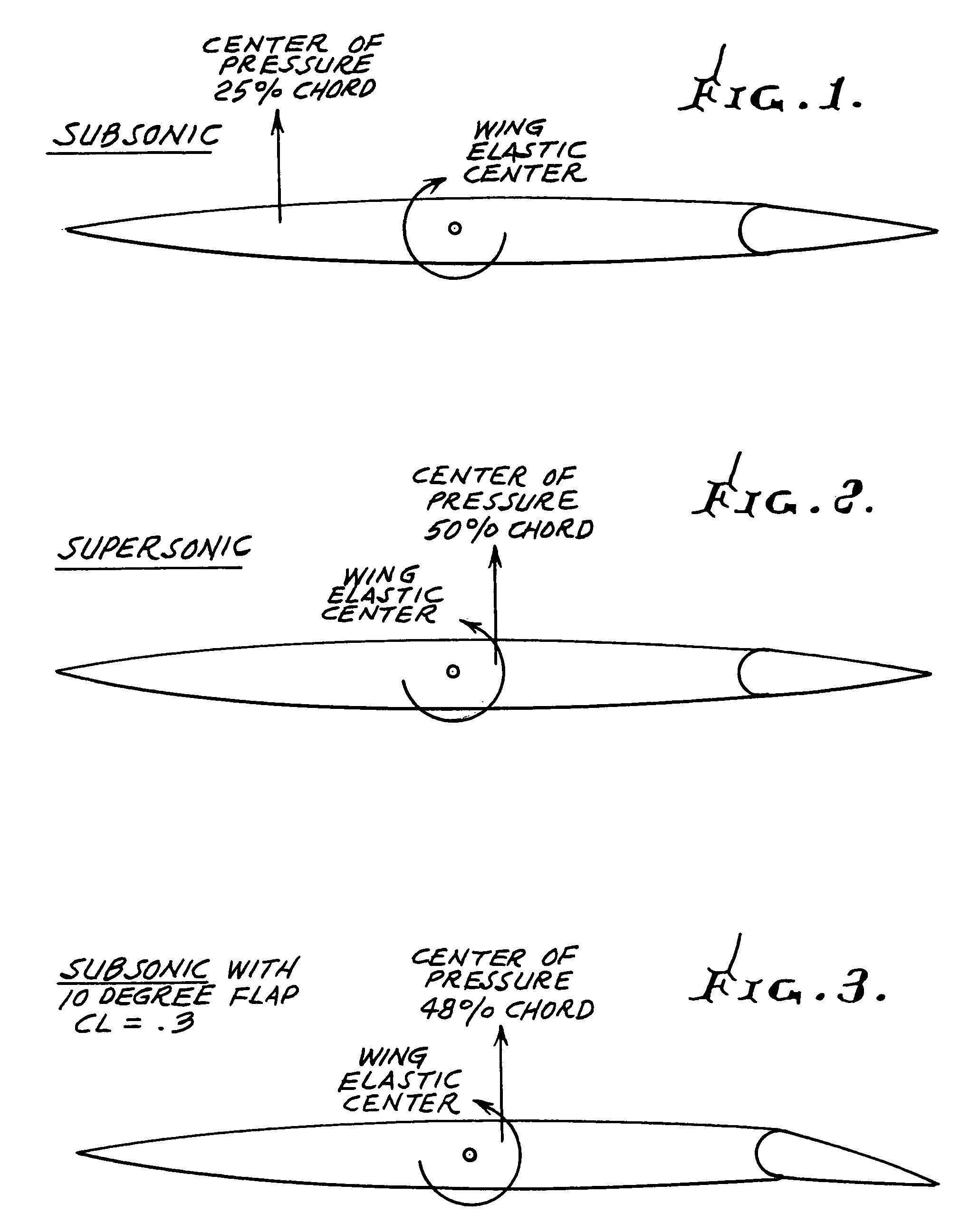
[0022]FIGS. 1–3 illustrate the conditions referred to above. To repeat, supersonic aircraft designed with thin, low sweep wings designed for extensive natural laminar flow tend to have low torsional stiffness. In subsonic flight (see FIG. 1) the center of pressure is typically ahead of the wing torsional elastic center creating a moment twisting the wingtip to higher angle of attack—“wash-in”. At supersonic conditions (see FIG. 2) the center of pressure is much closer to the wing elastic center, reducing or reversing the “wash-in”. A wing with a twist distribution optimized for supersonic cruise will thus have significant “wash-in” at subsonic speeds. This induces pre-mature tip stall, reducing the maximum achievable wing lift and creating undesirable control characteristics, at stall.

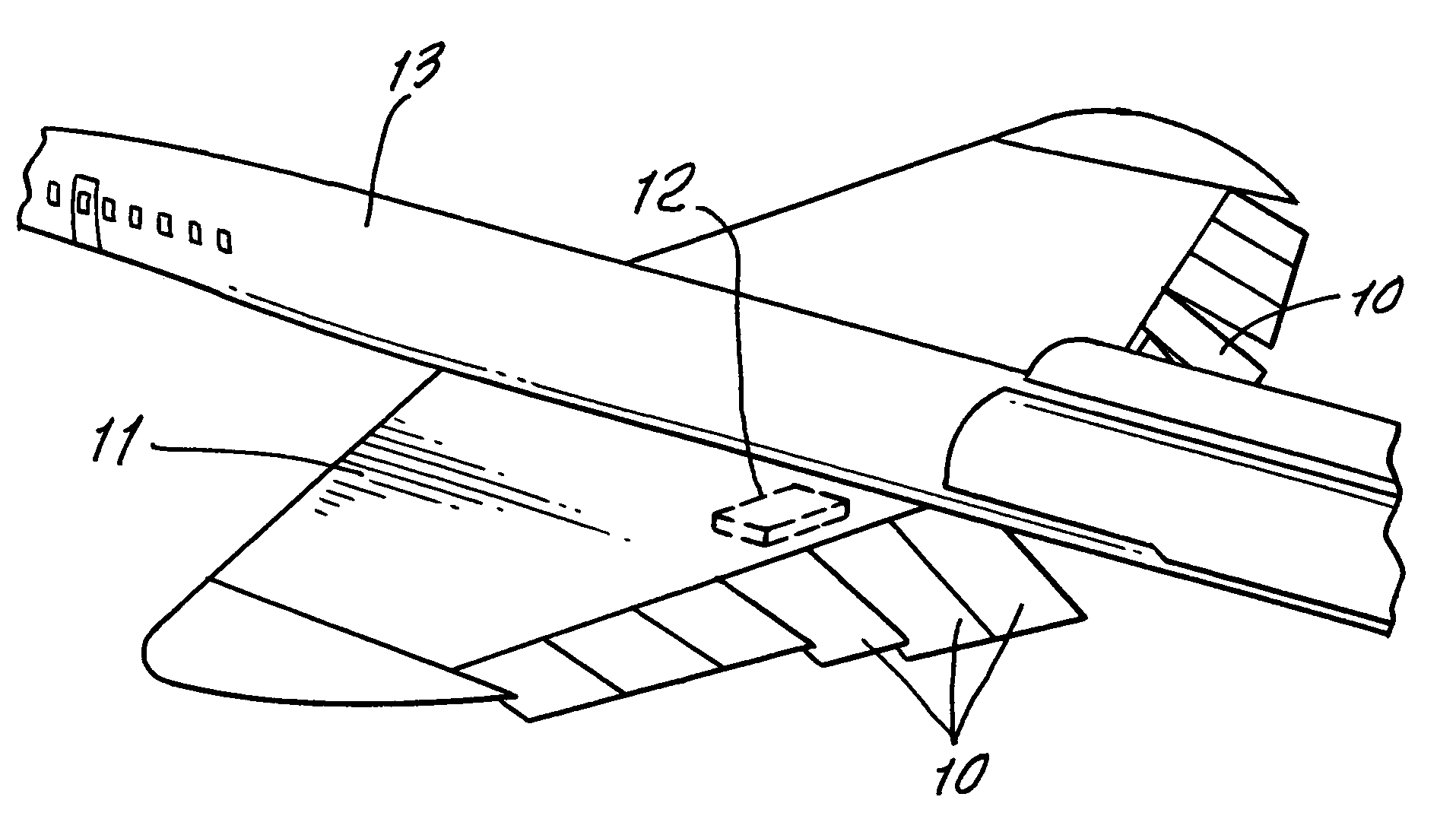
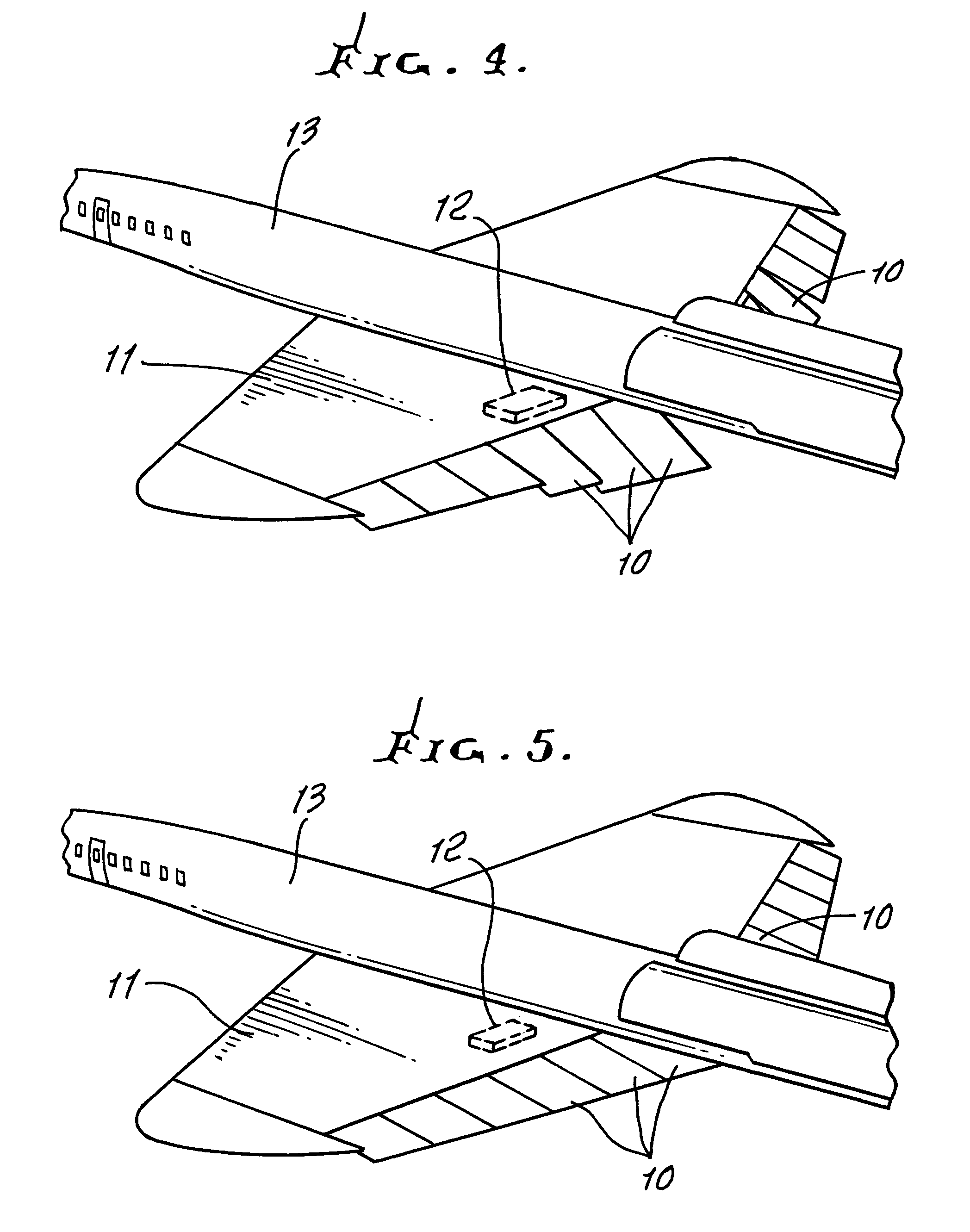
[0023]The present invention provides trailing edge flaps 10 on thin supersonic wings 11 with deflections scheduled to simultaneously control wing twist and reduce drag when operated at subsonic conditi...


PUM


Abstract

An aircraft includes a fuselage, thin supersonic wings on the fuselage, there being trailing edge flaps carried by the wings, the flaps configured to provide flap deflection to simultaneously control wing twist and to reduce drag, when the aircraft is operated at subsonic flight conditions.

Description

BACKGROUND OF THE INVENTION[0001]This application is a non-provisional application based on provisional application Ser. No. 60 / 441,934, filed Jan. 24, 2003.[0002]Supersonic aircraft designed with thin, low sweep wings designed for extensive natural laminar flow tend to have low torsional stiffness. In subsonic flight the center of pressure is typically ahead of the wing torsional elastic center creating a moment twisting the wingtip to higher angle of attack—“wash-in”. At supersonic conditions the center of pressure is much closer to the wing elastic center, reducing or reversing the “wash-in”. A wing with a twist distribution optimized for supersonic cruise will thus have significant “wash-in” at subsonic speeds. This induces pre-mature tip stall, reducing the maximum achievable wing lift and creating undesirable control characteristics, at stall.[0003]Thin supersonic airfoil sections with low camber also have significant drag penalties at subsonic conditions due leading edge vort...

Claims


Application Information

Patent Timeline
Patent Type & Authority Patents(United States)
IPC IPC(8): B64C9/06B64C3/50B64C9/18B64C30/00
CPCB64C3/50B64C9/18B64C30/00Y02T50/32Y02T50/145Y02T50/10Y02T50/30
Inventor TRACY, RICHARD R.CHASE, JAMES D.
Owner AERION INTPROP MANAGEMENT CORP
Why Eureka
Try Eureka