

Combustion gas seal for injector
a gas seal and combustion gas technology, applied in the direction of hose connections, machines/engines, braking systems, etc., can solve the problems of reducing clamping force and degrading sealing performance, and achieve the effect of preventing abnormal deformation
- Summary
- Abstract
- Description
- Claims
- Application Information
AI Technical Summary
Benefits of technology
Problems solved by technology
Method used
Image

Examples
first embodiment
(First Embodiment)
[0042]A combustion gas seal for injectors, according to a first embodiment of the invention, will be explained referring to FIGS. 1 to 5.
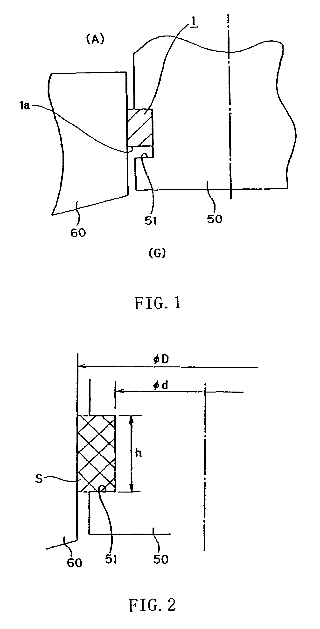
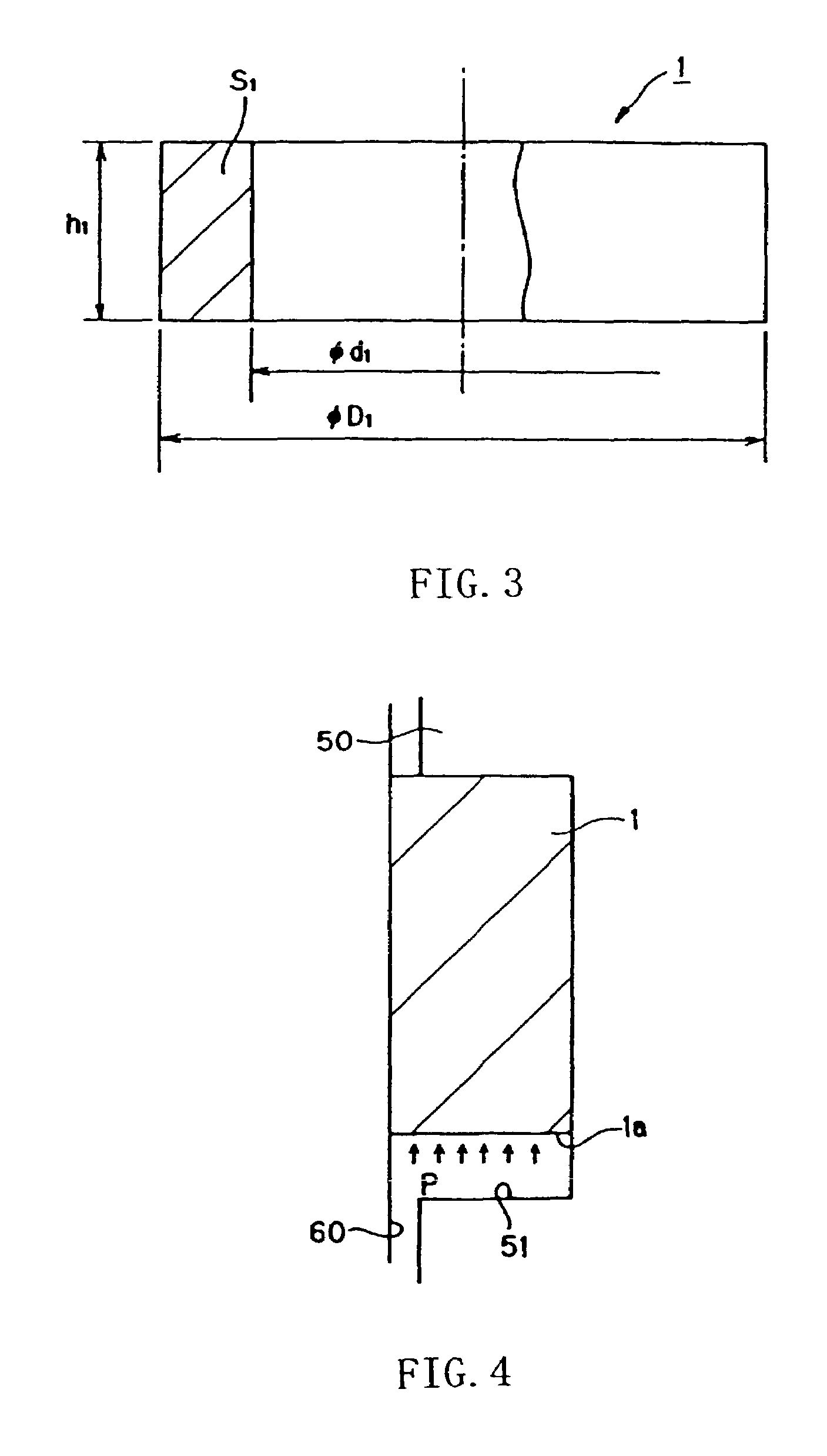
[0043]FIG. 1 is a schematic, cross sectional view showing a state, in which the combustion gas seal for injectors, according to the first embodiment of the invention, is attached. FIG. 2 is a schematic, cross sectional view showing a mating structure (a structure of an injector and a cylinder head), on which the combustion gas seal for injectors, according to the embodiment of the invention, is mounted. FIG. 3 is a cross sectional view showing the combustion gas seal for injectors, according to the first embodiment of the invention, with a part thereof broken away. FIG. 4 is a partially enlarged view of FIG. 1. FIG. 5 is a view illustrating a surface-pressure distribution.
[0044]A combustion gas seal 1 for injectors, according to the embodiment, serves to seal an annular gap between an injector 50 (outer periphery thereof) and a cy...
second embodiment
(Second Embodiment)
[0059]FIG. 6 shows a second embodiment. An explanation will be given to a constitution of the embodiment in the case where a U-shaped groove is provided on the combustion gas side end surface.
[0060]Since the other constitution and effect are the same as those in the first embodiment, the same characters denote the same constituents and an explanation therefor is omitted.
[0061]FIG. 6 is a schematic, cross sectional view showing a state, in which a combustion gas seal for injectors, according to the second embodiment of the invention, is attached.
[0062]In the embodiment, a U-shaped groove 11 opened toward the combustion gas side is provided over an entire periphery of a combustion gas side end surface of a combustion gas seal 10 for injectors.
[0063]Thereby, since pressure of a combustion gas acts on wall surfaces of the groove, surface pressures on the groove bottom portion of the attachment groove 51 of the injector 50 and the inner peripheral surface of the cylind...
third embodiment
(Third Embodiment)
[0066]FIG. 7 shows a third embodiment. An explanation will be given to a constitution of the embodiment in the case where a tapered surface is provided on a periphery of an inner-peripheral side end edge of the end surface on the combustion gas side.
[0067]Since the other constitution and function are the same as those in the first embodiment, the same characters denote the same constituents and an explanation therefor is omitted.
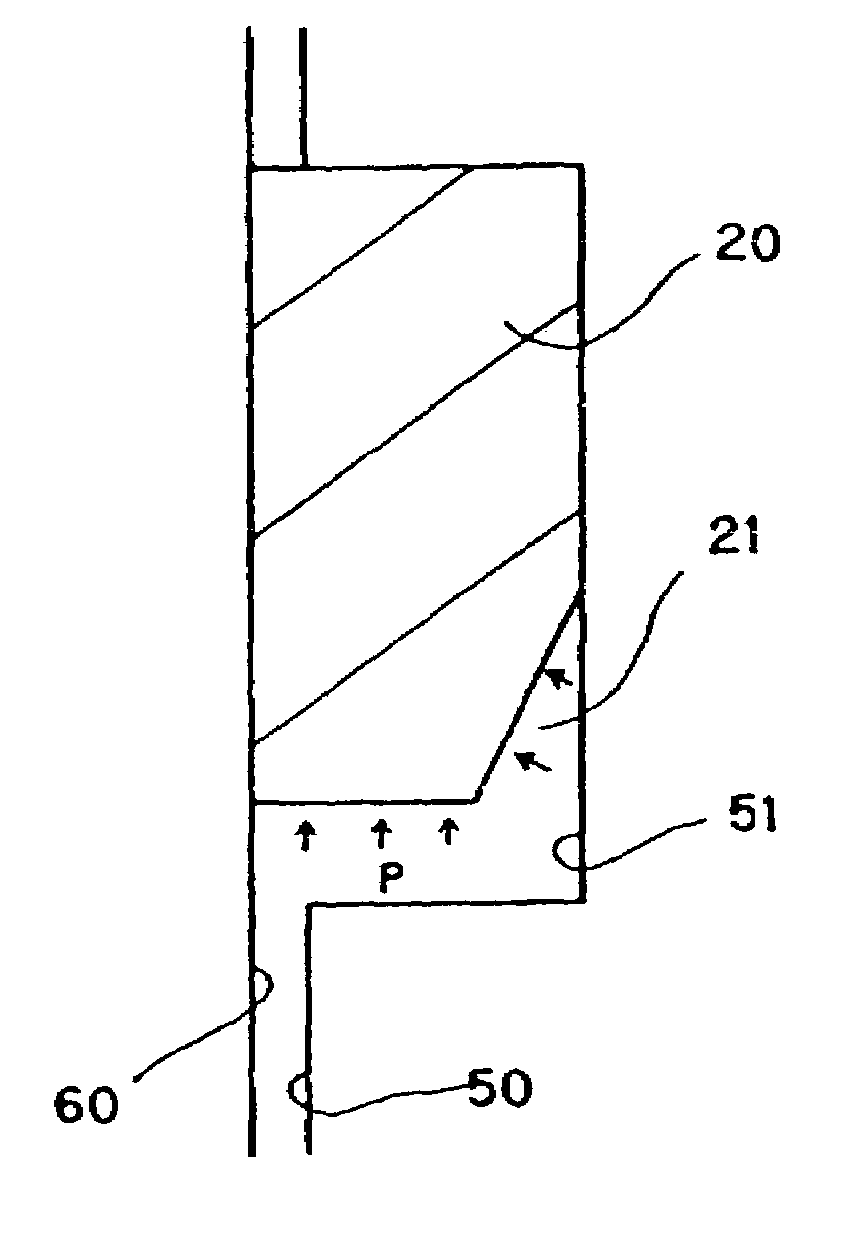
[0068]FIG. 7 is a schematic, cross sectional view showing a state, in which a combustion gas seal for injectors, according to the third embodiment of the invention, is attached.
[0069]In the embodiment, a tapered surface 21 is provided on an entire periphery of an inner-peripheral side end edge of the end surface on the combustion gas side of a combustion gas seal 20 for injectors.
[0070]Thereby, since pressure of a combustion gas acts on the tapered surface 21, component forces toward an outer peripheral side is generated and a surface press...
PUM
 Abstract
Description
Claims
Application Information