Liquid crystal projector

a liquid crystal and projector technology, applied in projectors, color television details, instruments, etc., can solve the problems of large distance between the projection lens and the liquid crystal elements, difficult adjustment, widening the projection lens angle, etc., and achieves the effect of high quality and easy mounting

Inactive Publication Date: 2006-02-28
FUJI PHOTO OPTICAL CO LTD
View PDF4 Cites 7 Cited by
  • Summary
  • Abstract
  • Description
  • Claims
  • Application Information

AI Technical Summary

Benefits of technology

[0007]In view of the foregoing, a primary object of the present invention is to provide a liquid crystal projector that can be easy to assemble, and achieves high quality of the image on the screen.
[0010]According to the present invention, the front lens group and the rear lens groups are mounted to the frames that are formed on the prism base plate to which the color recombination prism is fixed. Therefore, the lens elements of the projection lens can be easy to mount without the need for any complicated fine adjustment. Because the projection lens is constituted of the front lens group and the first and the second rear lens groups, it is possible to correct the respective color images through the rear lens groups. So the full-color image projected on the screen can achieve a high quality.

Problems solved by technology

However, because the projector using the reflective liquid crystal elements needs a polarizing beam splitter prism in addition to the color recombination prism, the distances between the projection lens and the liquid crystal elements are inevitably large.
This is disadvantageous for the sake of widening the angle of the projection lens.
Because it is difficult to adjust the positions of the front and the rear lens groups to each other, and also because it is hard to increase the number of lens elements of the rear lens group, the front and the rear lens groups are conventionally held in their individual holders, and these lens holders are mounted on a prism base plate that holds the recombination prism.
For this reason, the assembling process of the projection lens has been difficult.

Method used


Image

  • Liquid crystal projector
  • Liquid crystal projector
  • Liquid crystal projector

Examples


Embodiment Construction

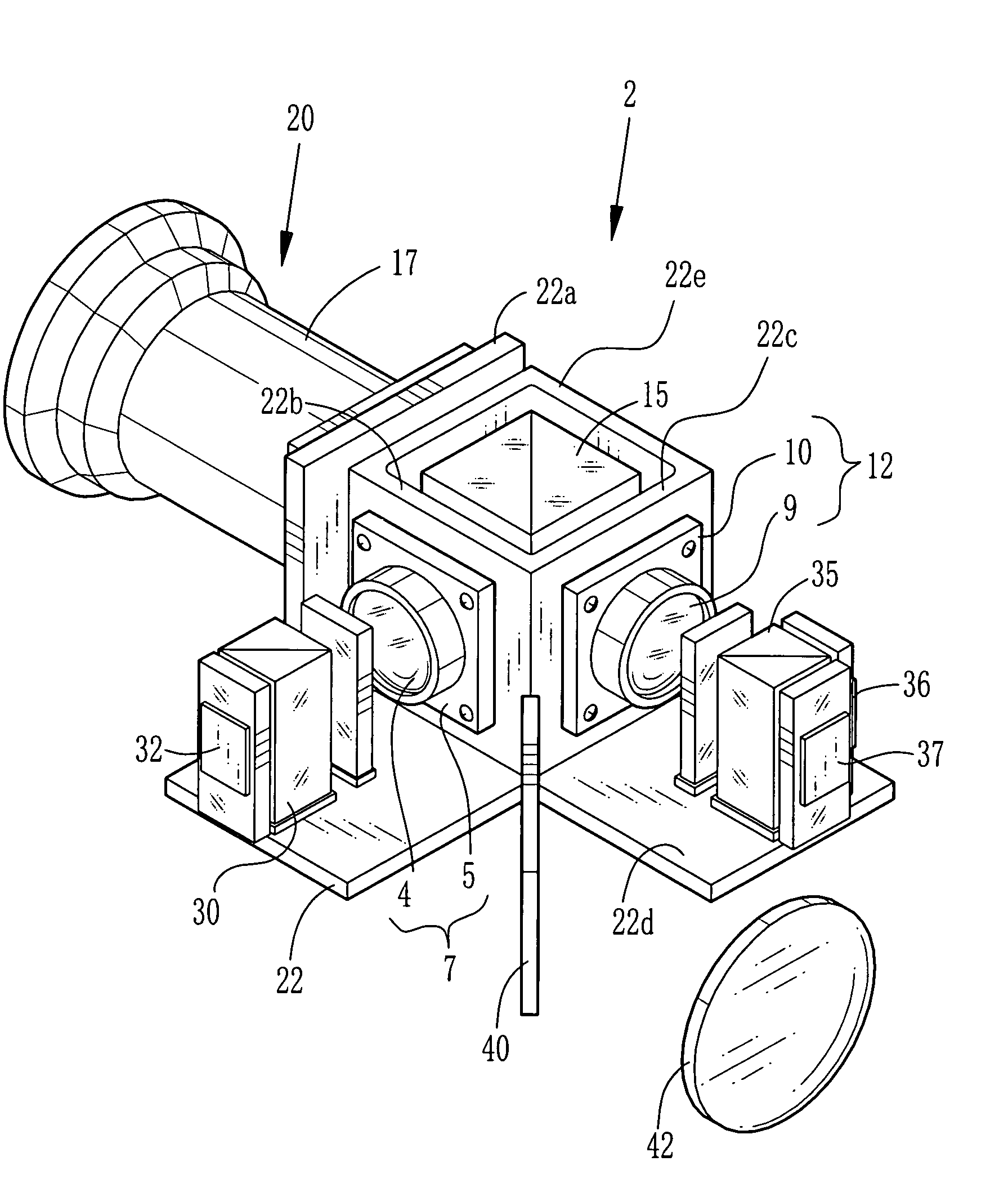
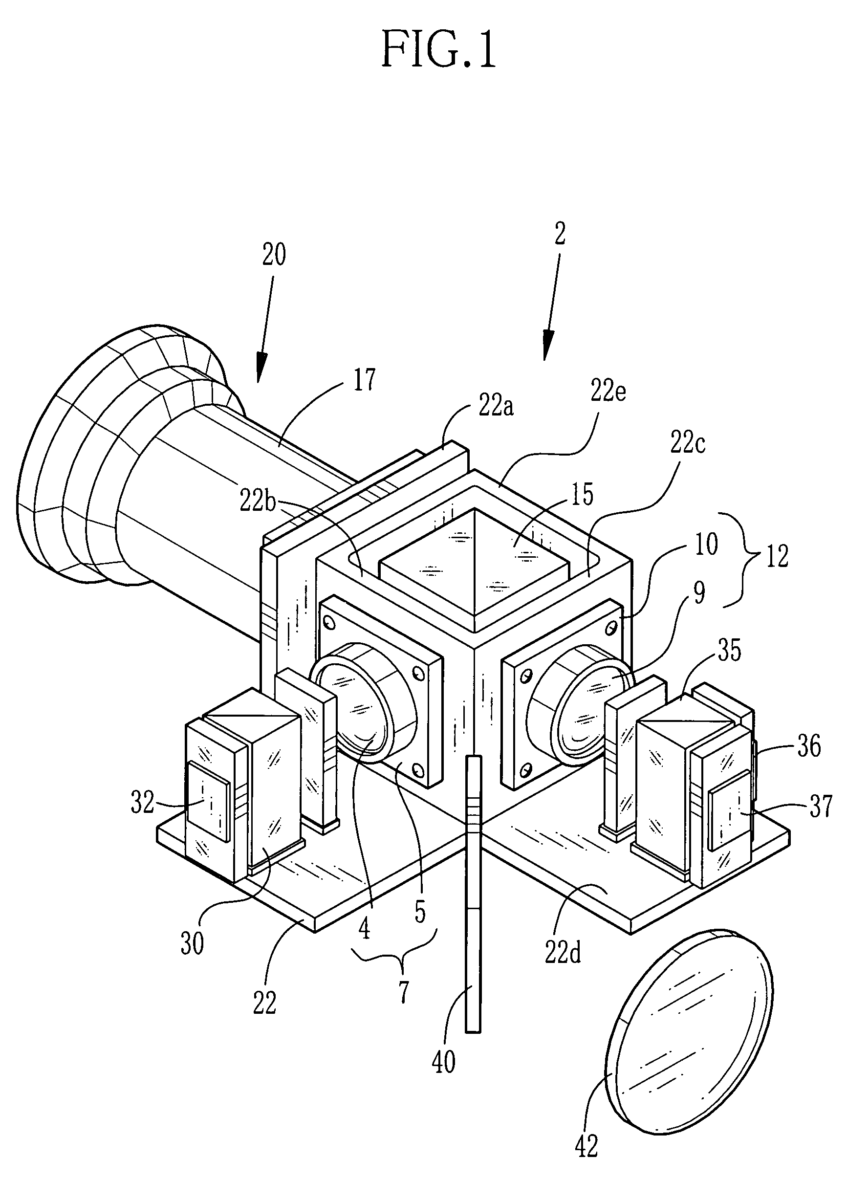
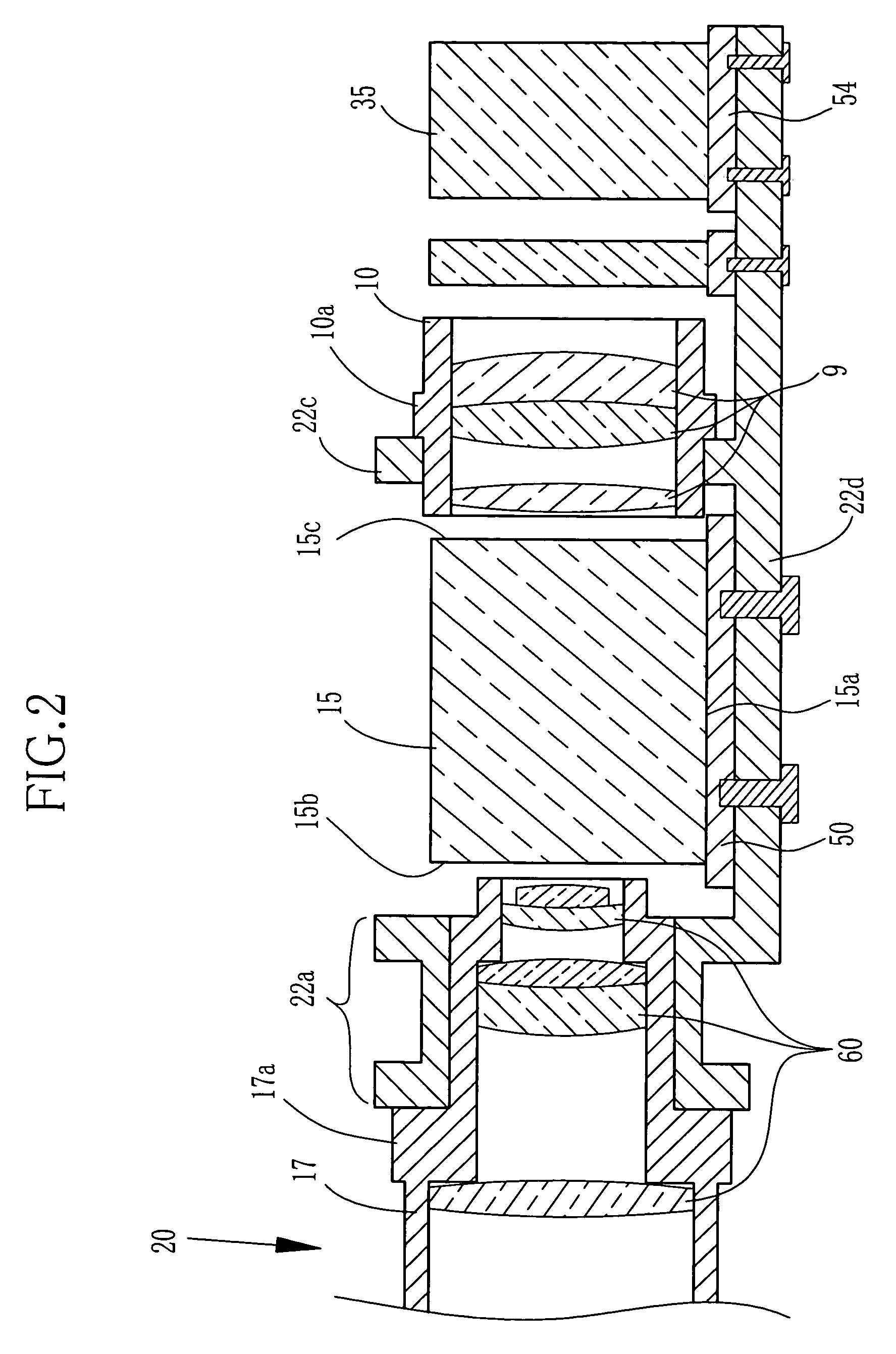
[0017]In a liquid crystal projector 2 shown in FIG. 1, a first rear lens unit 7 consists of a first rear lens group 4 held in a holder 5, a second rear lens unit 12 consists of a second rear lens group 9 held in a holder 10, and a front lens unit 20 consists of a front lens group 60 (see FIG. 2) held in a lens barrel 17. These lens units 7, 12 and 20 are mounted on a base body 22.

[0018]The base body 22 consists of a prism base plate 22d having a smooth surface, three frames 22a, 22b and 22c, and a plate member 22e. A base surface of a rectangular recombination prism 15 is fixed to the prism base plate 22d. The first to third frames 22a to 22c and the plate member 22e are placed in opposition to and in parallel to four side surfaces of the recombination prism 15 respectively. The first to third frames 22a to 22c and the plate member 22e are coupled to each other to form a rectangular tube.

[0019]The first rear lens group 4 includes a number of lens elements whose optical axes are adju...


PUM

PropertyMeasurementUnit
coloraaaaaaaaaa
opticalaaaaaaaaaa
colorsaaaaaaaaaa

Abstract

A liquid crystal projector of three-color type has three liquid crystal elements for modulating three primary color light bundles into three color optical images respectively. A recombination prism combines modulated three color optical images, and a projection lens system projects the combined full-color image on a screen. The projection lens system is constituted of the front lens group and the first and second rear lens groups. The front lens group and the rear lens groups are mounted to frames that are formed integrally on a prism base plate to which the recombination prism is fixed.

Description

FIELD OF THE INVENTION[0001]The present invention relates to a liquid crystal projector is provided with three panels of liquid crystal elements for modulating light bundles of three primary colors, i.e. blue, green and red, into three color optical images, wherein the three color optical images are combined to display a full-color image on a screen.BACKGROUND ARTS[0002]The liquid crystal projector is mainly constituted of a light source, color separating optical elements, such as a dichroic mirror, liquid crystal elements, a color recombination prism, a projection lens. White light from the light source is separated through the color separation optical elements into light bundles of three primary colors. The three color light bundles are directed to the three liquid crystal elements respectively. The liquid crystal elements modulate the three color light bundles and output the modulated light bundles as optical images of three primary colors to the recombination prism, where the th...

Claims


Application Information

Patent Timeline
Patent Type & Authority Patents(United States)
IPC IPC(8): G03B21/14G02F1/13G02F1/1335G03B21/00G03B21/10G03B21/20G03B21/28
CPCG03B21/20G03B21/28G03B21/006H04N9/317H04N9/3105
Inventor SHIMIZU, HITOSHI
Owner FUJI PHOTO OPTICAL CO LTD
Why Eureka
Try Eureka