

Belt type infinite variable-speed drive
- Summary
- Abstract
- Description
- Claims
- Application Information
AI Technical Summary
Benefits of technology
Problems solved by technology
Method used
Image

Examples
Embodiment Construction
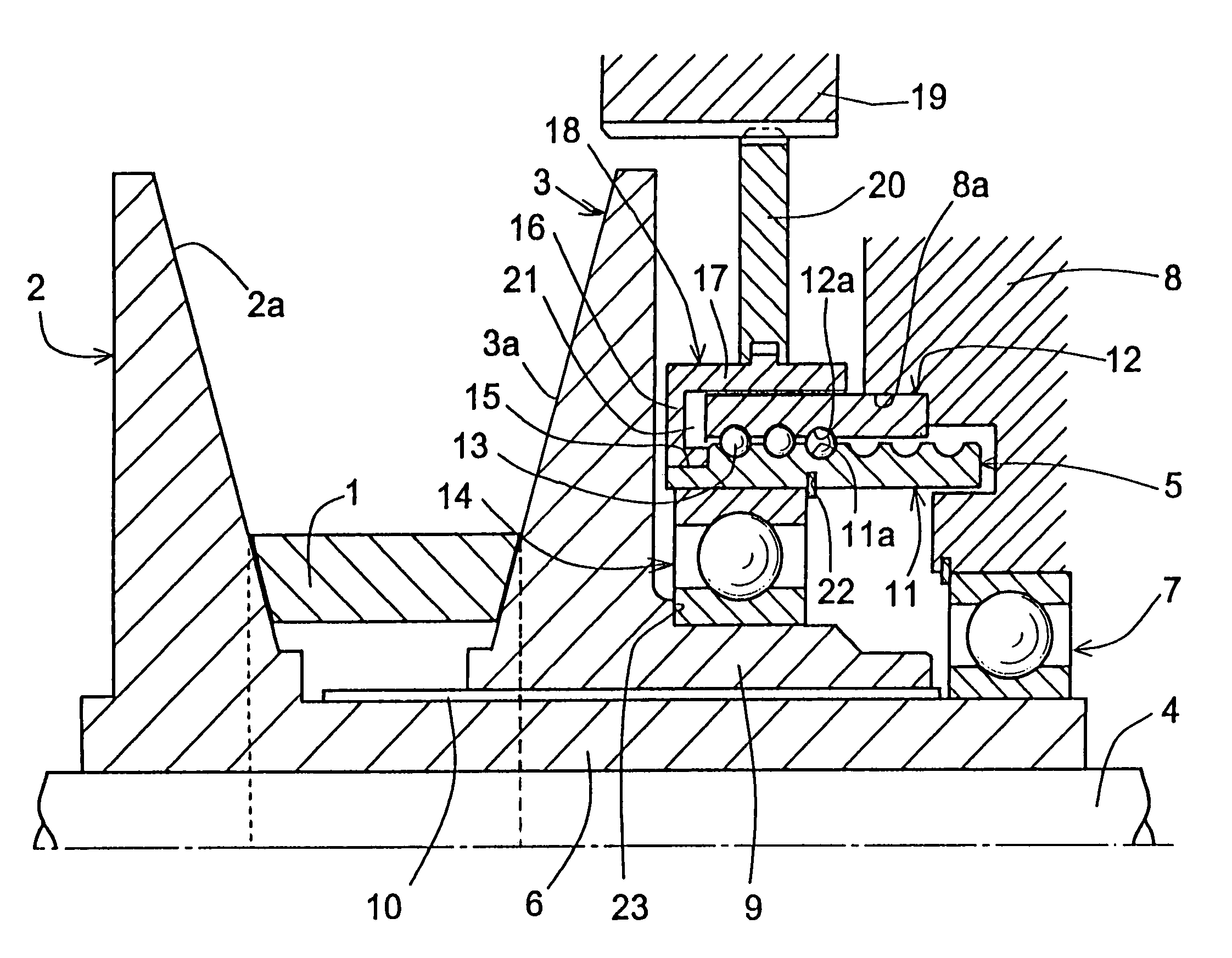
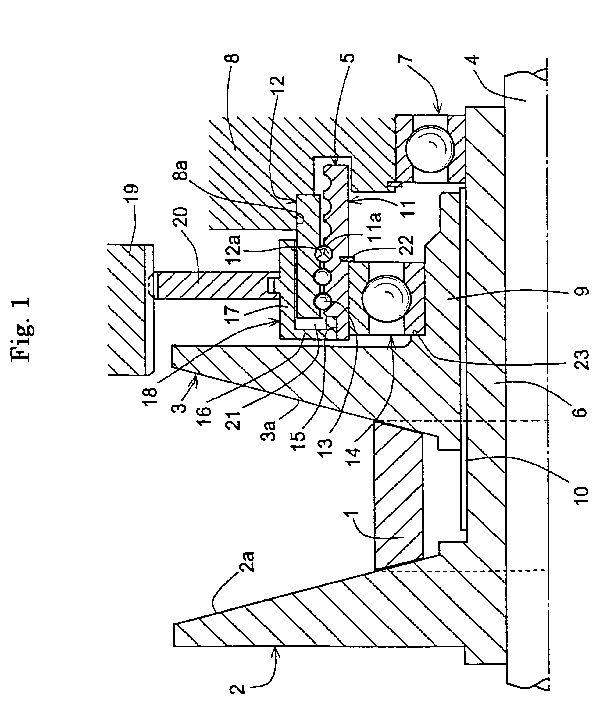
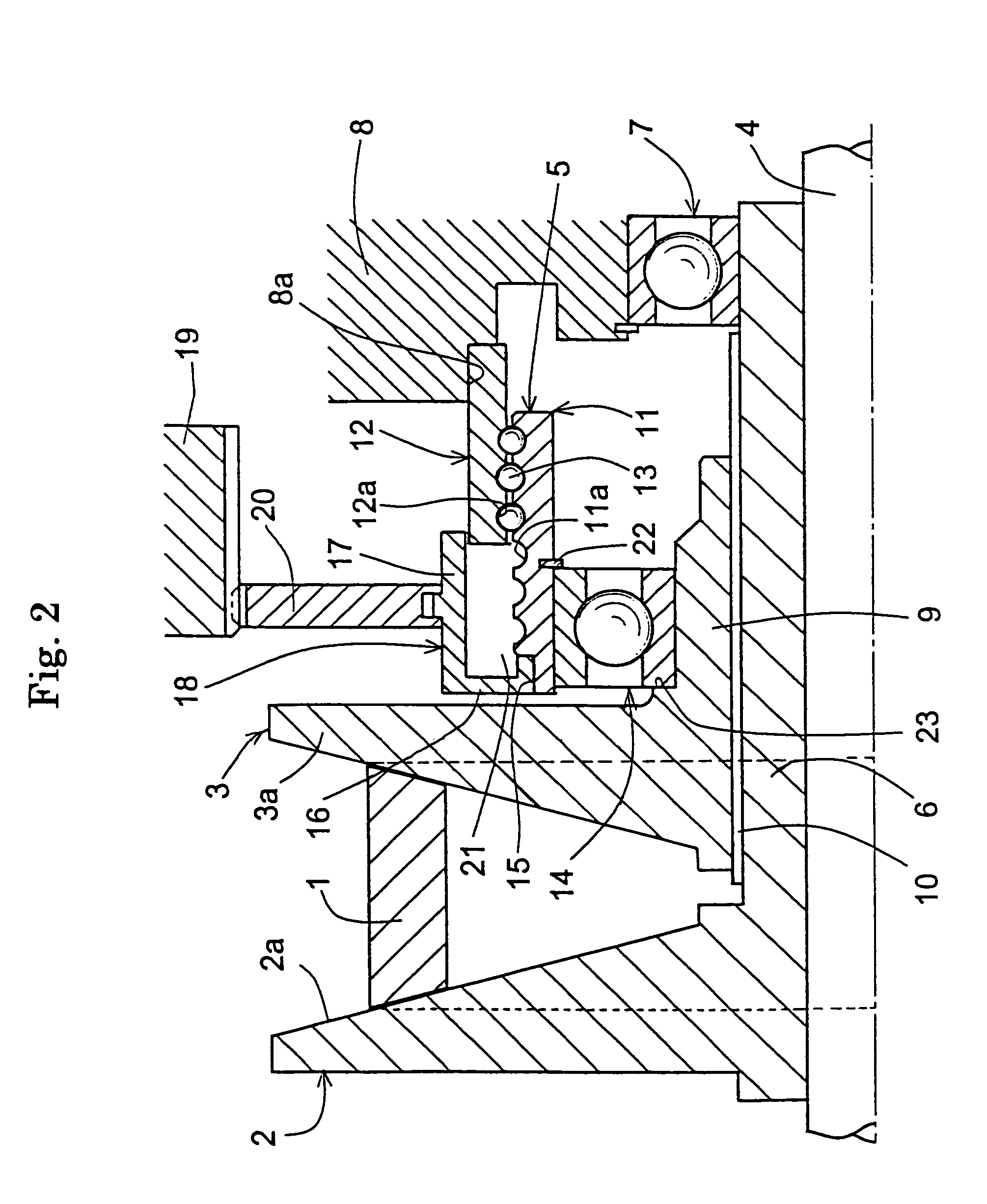
[0027]Embodiments of this invention will be described with reference to FIGS. 1–5. FIGS. 1–3 show a first embodiment. As shown in FIG. 1, in this belt type infinite variable-speed drive, a pulley is defined by a fixed pulley member 2 and a movable pulley member 3, around which pulley is wound a transmission belt 1. The fixed pulley member 2 and the movable pulley member 3 are mounted on a rotary shaft 4 with their belt-receiving surfaces 2a, 3a facing each other. By axially moving the movable pulley member 3 by virtue of a ball-screw mechanism 5, a winding diameter of the transmission belt 1 is changed in a stepless manner.
[0028]The fixed pulley member 2 is provided with a tubular portion 6 extending toward the movable pulley member 3, and is coupled through a key to the rotary shaft 4 so as to rotate therewith. The rotary shaft 4 has its movable pulley member side supported on a casing 8 by a ball bearing 7 mounted on a tip of the tubular portion 6. Although not shown, the fixed pu...
PUM
 Abstract
Description
Claims
Application Information