Intake air pre-cleaner with aspirator port chamber for collecting and holding particles for later aspiration

a pre-cleaner and air intake technology, applied in the field of pre-cleaners, can solve the problems of affecting the operation of the pre-cleaner, and removing the power of the engine, and achieving the effect of reducing the cost of operation

Inactive Publication Date: 2006-02-28
CNH IND AMERICA LLC +1
View PDF10 Cites 33 Cited by
  • Summary
  • Abstract
  • Description
  • Claims
  • Application Information

AI Technical Summary

Benefits of technology

[0006]As a result, even during periods of prolonged low suction operation, such as when the engine is idling for a long period of time under high airborne dust conditions, clogging of the pre-cleaner and particularly the aspira

Problems solved by technology

A disadvantage of dust disposal arrangements such as that of the Roach et al. patent is the requirement of the blower, which adds expense and complexity, takes power from the engine, and any failure or inadequate operation of which can have severe operational consequences.
A shortcoming of this manner of disposal, however, is the evident limited dust disposal capacity and thus a resultant lack of utility for extremely dusty applications as can be encountered such as for use on agricultural harvesting machines such as combines and cotton pickers, which are known to be used in environments so dusty that

Method used


Image

  • Intake air pre-cleaner with aspirator port chamber for collecting and holding particles for later aspiration
  • Intake air pre-cleaner with aspirator port chamber for collecting and holding particles for later aspiration
  • Intake air pre-cleaner with aspirator port chamber for collecting and holding particles for later aspiration

Examples


Embodiment Construction

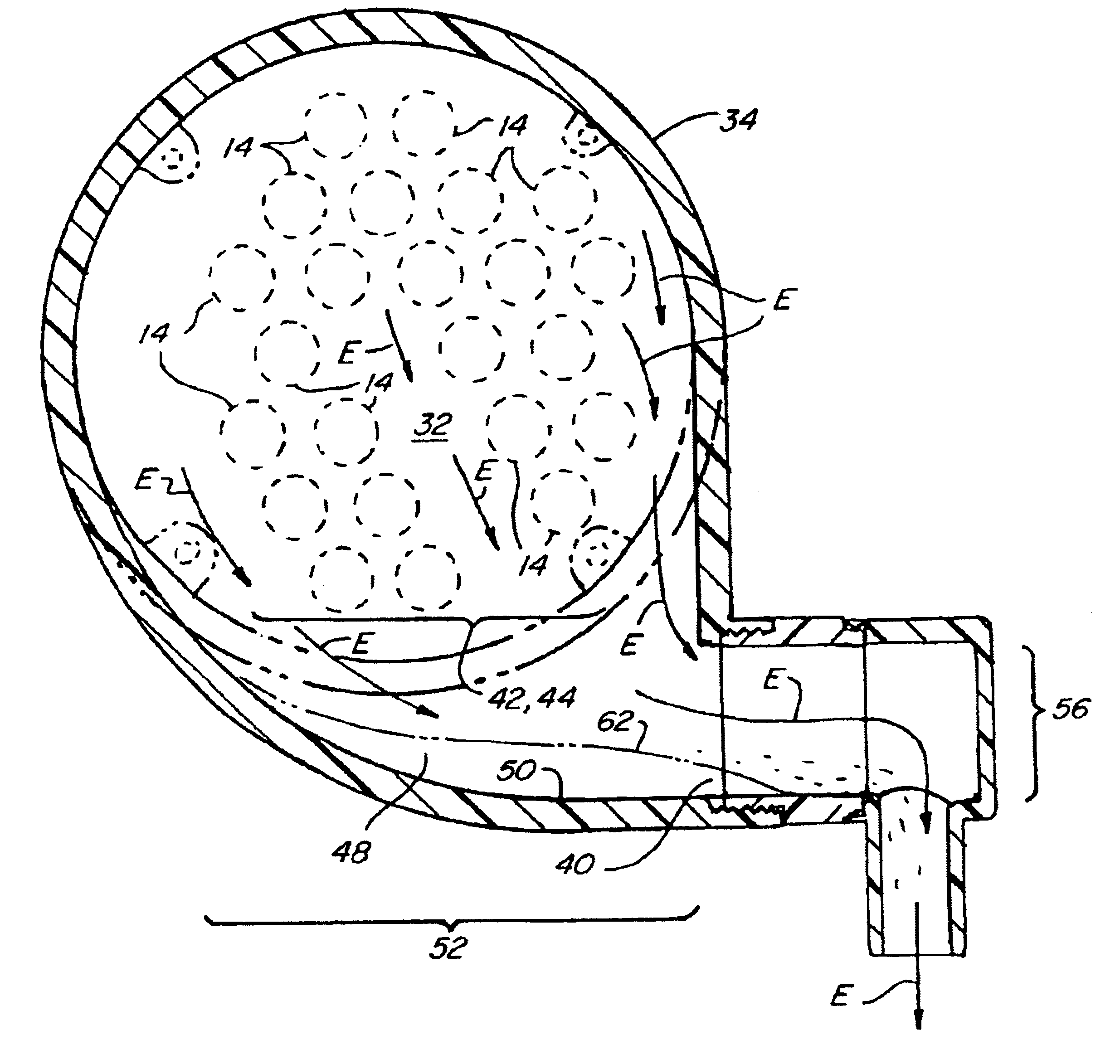
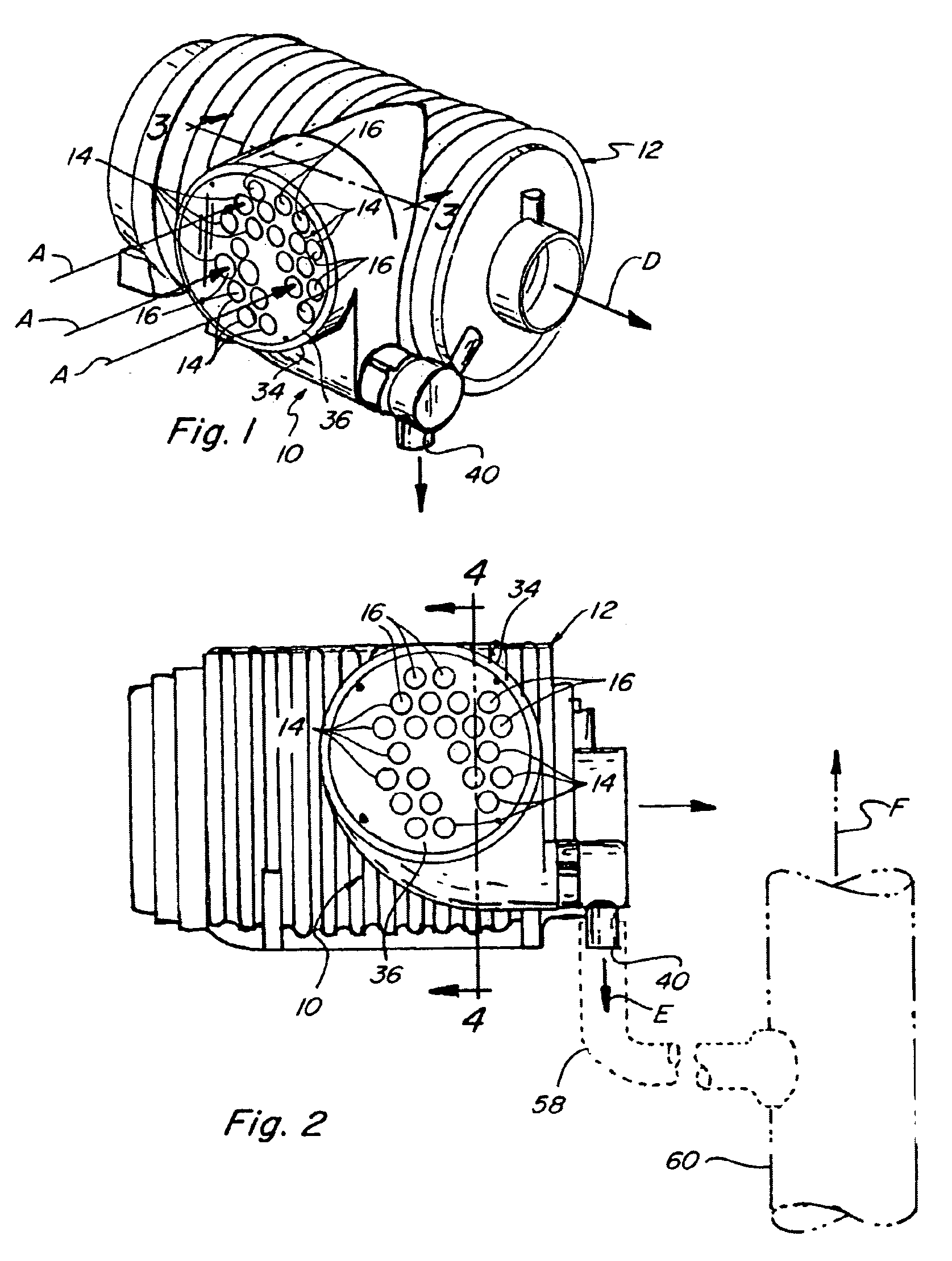
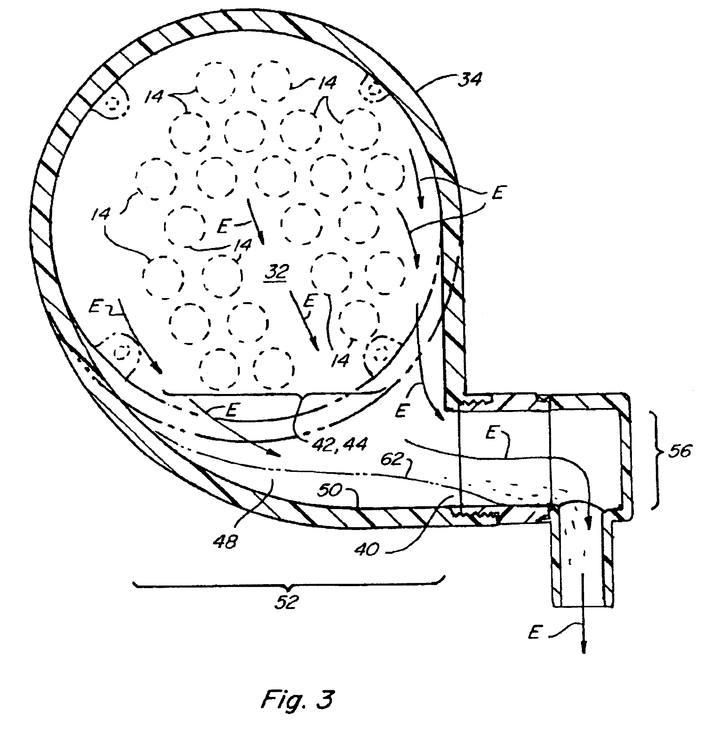
[0011]Referring now to the drawings, in FIGS. 1 and 2, a pre-cleaner 10 is shown in association with a conventional air cleaner 12 for removing particulates such as fine dust, sand, and plant matter from air entering an intake or induction system of an internal combustion engine (not shown) of a machine such as an agricultural combine, a construction machine, or the like (also not shown). Pre-cleaner 10 includes a plurality of particulate separator tubes 14 arranged in a predetermined array and including respective air inlets 16 for receiving individual flows of air, represented by arrows A, from atmosphere.

[0012]Referring to FIG. 4, each particulate separator tube 14 of pre-cleaner 10 is hollow so as to define an air flow passage 18 therethrough including vanes 20 for inducing air flow A into a spiral or vortex flow pattern such that particles such as fine dust and the like suspended in air flow A through passage 18 will be separated from the flow by centrifugal force and ejected o...


PUM

PropertyMeasurementUnit
Angleaaaaaaaaaa
Flow rateaaaaaaaaaa
Shapeaaaaaaaaaa

Abstract

A pre-cleaner for an air induction system of an internal combustion engine including a housing enclosing an upper chamber and an aspirator port chamber, the upper chamber containing a plurality of particulate separator tubes for removing particles from air flowing through the tubes en route to the engine. The aspirator port chamber is located beneath and is upwardly open to the particulate outlets such that discharged particles can fall or flow from the tubes into the aspirator port chamber, the aspirator port chamber containing a large capacity upwardly facing particle collecting surface or trough for receiving the particles, and the housing including a generally horizontally facing aspirator port connecting to the aspirator port chamber adjacent to the particle collecting surface or trough, the aspirator port having a predetermined vertical extent and the particle collecting surface or trough having a horizontal extent in a direction substantially directly facing or aligned with the aspirator port sufficiently greater than the vertical extent of the aspirator port such that during periods when the particles are not aspirated into the aspirator port the particles can collect and settle on the particle collecting surface or trough for later aspiration when conditions improve.

Description

TECHNICAL FIELD[0001]This invention relates generally to pre-cleaner devices for air entering the intake or induction tract of an internal combustion engine, and more particularly, to a pre-cleaner for separating dust and other particulates from a flow of air entering the intake tract and aspirating the separated particulates into the engine exhaust, the pre-cleaner having an improved aspirator port chamber which substantially reduces the possibility of blocking and clogging by the particulates of an aspirator port connected to the engine exhaust and other regions of the pre-cleaner during periods of poor aspiration.BACKGROUND ART[0002]Airborne particulates, such as fine dust, dirt, sand, crop material, and the like, must be separated from air entering an internal combustion engine such that the particulates do not travel on to clog passages within the engine and / or cause significant damage thereto. A well known manner of separating such particulates from the air flow is to cause th...

Claims


Application Information

Patent Timeline
IPC IPC(8): B01D45/12B01D45/16F02M35/022
CPCF02M35/022B01D45/16Y02A50/2351
Inventor PIKESH, DERRYN W.CARLZ, RANDY
Owner CNH IND AMERICA LLC
Why Eureka
Try Eureka