Lead configuration for inline packages

a technology of inline packages and lead configuration, applied in the direction of electrical equipment, semiconductor devices, semiconductor/solid-state device details, etc., can solve the problems of excessive thermal cycling of ic power packages, short packages, and various drawbacks of packages, so as to reduce parasitic electrical effects, shorten wire bonds, and mitigate delamination and its accompanying problems

Active Publication Date: 2006-02-28
NAT SEMICON CORP
View PDF12 Cites 12 Cited by
  • Summary
  • Abstract
  • Description
  • Claims
  • Application Information

AI Technical Summary

Benefits of technology

[0005]Broadly speaking, the invention pertains to leads and a die attach pad for use in inline power packages. The leads and / or die attach pad are configured with uneven edges, i.e., they are designed with protrusions and recesses that more securely adhere to encapsulant material, thus mitigating delamination and its accompanying problems. As an added advantage, such protrusions and recesses allow the leads to be placed closer to the die attach pad, allowing for shorter wire bonds and thus reducing any parasitic electrical effects. As a further added advantage, such a design also creates more sites for wirebonding to the leads, allowing adjacent wire bonds to be spaced farther apart so as to better avoid damage or interference.

Problems solved by technology

However, such packages suffer from various drawbacks.
As one example, it is known that the transport and control of electrical power can subject IC power packages to excessive thermal cycling as they heat up and cool down.
Such delamination allows moisture to enter the IC, which can corrode and / or short the package, and otherwise reduce performance.
Connecting and disconnecting the IC also generates stresses along the length of the leads, adding to the risk of delamination.

Method used


Image

  • Lead configuration for inline packages
  • Lead configuration for inline packages
  • Lead configuration for inline packages

Examples


Embodiment Construction

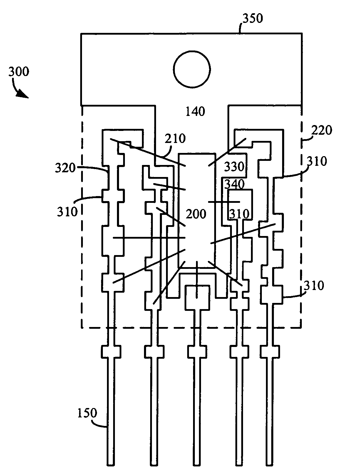
[0017]In one embodiment of the invention, a lead frame for use in an inline IC package is designed such that its die attach pad and leads each have a number of protrusions and recesses. These protrusions and recesses create an irregular surface that provides better adhesion to encapsulant material than conventional leads and die attach pads, whose smooth, straight surfaces risk delamination of the encapsulant material. Such a design provides additional benefits, such as the ability to design lead protrusions close to the die attach pad, where shorter bond wires can be used, thus reducing any parasitic inductance that may arise. Such protrusions and recesses also create more sites for wirebonding, allowing wire bonds to be spaced apart so as to better avoid damage or interference with adjacent wire bonds.

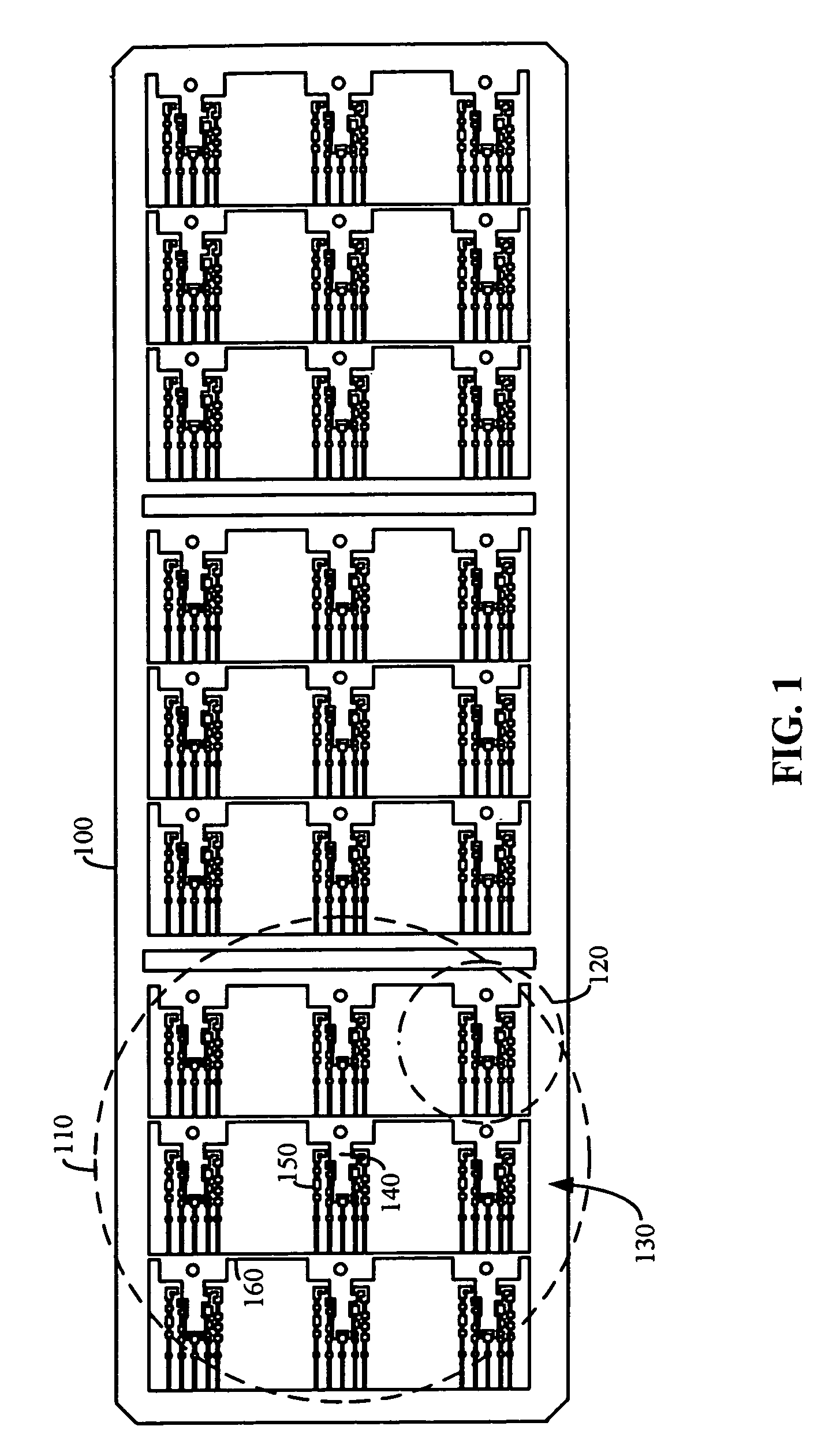
[0018]FIG. 1 illustrates an example of a lead-frame having leads and die attach pads employing such protrusions and recesses. The lead-frame 100 has a number of two dimensional array...


PUM


Abstract

A substrate for use in an inline IC package is designed such that its die attach pad and leads each have a number of protrusions and recesses. These protrusions and recesses create an irregular surface that provides better adhesion to encapsulant material than conventional leads and die attach pads, whose smooth, straight surfaces risk delamination of the encapsulant material.

Description

BRIEF DESCRIPTION OF THE INVENTION[0001]This invention relates to the packaging of integrated circuits (ICs). More specifically, this invention relates to the design of leads for use in inline IC packages.BACKGROUND OF THE INVENTION[0002]Current IC power packages, or those ICs designed to transport and / or regulate electrical power, are typically fabricated using a conductive lead-frame and leads surrounded by an encapsulant material, commonly a plastic. The encapsulant protects the IC and its integrated circuits from damage and environmental extremes, allowing such solid-state ICs to function in a robust manner. However, such packages suffer from various drawbacks.[0003]As one example, it is known that the transport and control of electrical power can subject IC power packages to excessive thermal cycling as they heat up and cool down. As the encapsulant and leads often undergo differing rates of thermal expansion, stresses can build up at their interfaces, causing delamination of t...

Claims


Application Information

Patent Timeline
Patent Type & Authority Patents(United States)
IPC IPC(8): H01L23/495
CPCH01L21/561H01L23/49541H01L23/49562H01L24/49H01L2924/01033H01L24/48H01L2224/48247H01L2224/49171H01L2924/01005H01L2924/01013H01L2924/01082H01L2924/14H01L2924/30107H01L2924/00H01L2924/00014H01L2924/181H01L2224/45099H01L2224/05599H01L2924/00012
Inventor LI, FELIX C.
Owner NAT SEMICON CORP
Why Eureka
Try Eureka