Substrate with reinforced contact pad structure

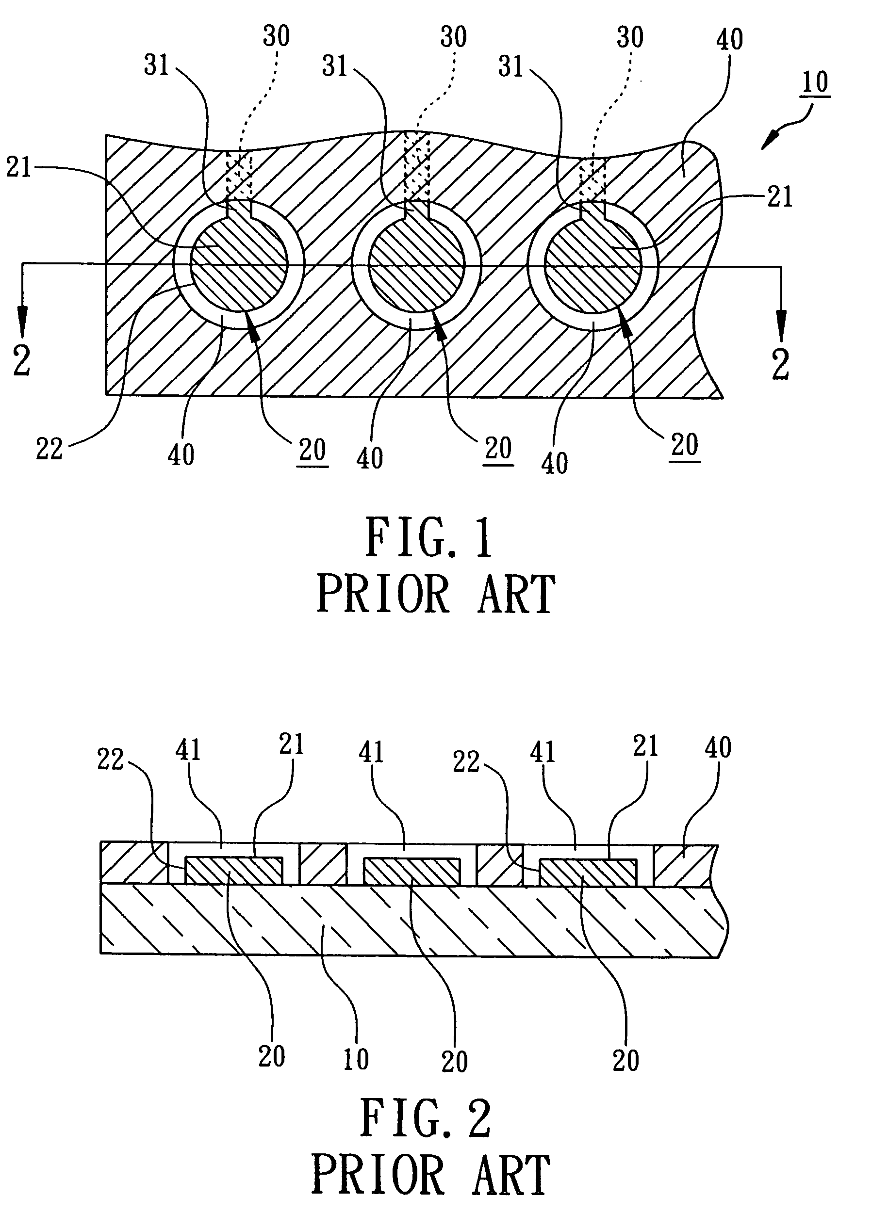
a contact pad and substrate technology, applied in the direction of printed circuit aspects, sustainable manufacturing/processing, final product manufacturing, etc., can solve the problems of poor adhesion or even failure, low assembly yield, traces b>30/b> to break or electrically fail, etc., to achieve the effect of greatly enhancing the connection strength between the trace 130 and the nsmd type contact pad 120, greatly enhancing the position stability and reliability of the nsmd type contact pad

Active Publication Date: 2006-02-28
ASE SHANGHAI
View PDF18 Cites 154 Cited by
  • Summary
  • Abstract
  • Description
  • Claims
  • Application Information

AI Technical Summary

Benefits of technology

[0004]The main purpose of the present invention is to provide a substrate with reinforced contact pad structure. An extension is extended from a NSMD contact pad on a substrate. Moreover, the extension connects a trace and has an upper surface which is covered by a solder mask to improve the connection strength between the trace and the NSMD contact pad and to improve the position stability of NSMD contact pad on the substrate.
[0005]The second purpose of the present invention is to provide a substrate with reinforced contact pad structure. An extension connecting a NSMD contact pad and an extensive gap of the solder mask opening are formed on the substrate in the staggered layout where the extensive gap exposes the sidewalls of the extension and the contact pad to compensate the area reduction of sidewall of the NSMD contact pad connected by the extension and to increase the reliability of electrical connection of bump, solder ball or solder paste.
[0006]According to the present invention, a substrate with the reinforced contact pad structure is provided, including a substrate, a metal wiring layer, and a solder mask. The metal wiring layer is disposed on the surface of the substrate and includes at least a contact pad, a trace and at least an extension connecting the contact pad and the trace. The contact pad has a bonding surface and a sidewall. The solder mask is formed over the surface of the substrate to cover the upper surface of the extension and the trace. The solder mask has at least an opening to expose the bonding surface and the sidewall of the contact pad. Preferably, the sidewall of the extension is also exposed out of the opening of the solder mask. Thus the extension connects the trace and has the upper surface covered by the solder mask to improve the connection strength between the trace and the contact pad and to improve the position stability of the contact pad on the substrate.

Problems solved by technology

However, since the edge of the opening of the solder mask will contact with bumps, solder balls or solder paste, therefore, bumps, solder balls or solder paste will experience extra stress from the solder mask which will cause poor adhesion or even failure which is revealed in Taiwan Patents No. 441059.
This will easily cause the traces 30 to break or electrically fail.
Moreover, because contact pads 20 are completely exposed out of the solder mask 40, therefore, the positions of contact pads 20 on the substrate 10 may be shifted which will cause alignment problems in the following assembly processes and the assembly yield will be low.

Method used


Image

  • Substrate with reinforced contact pad structure
  • Substrate with reinforced contact pad structure
  • Substrate with reinforced contact pad structure

Examples


Embodiment Construction

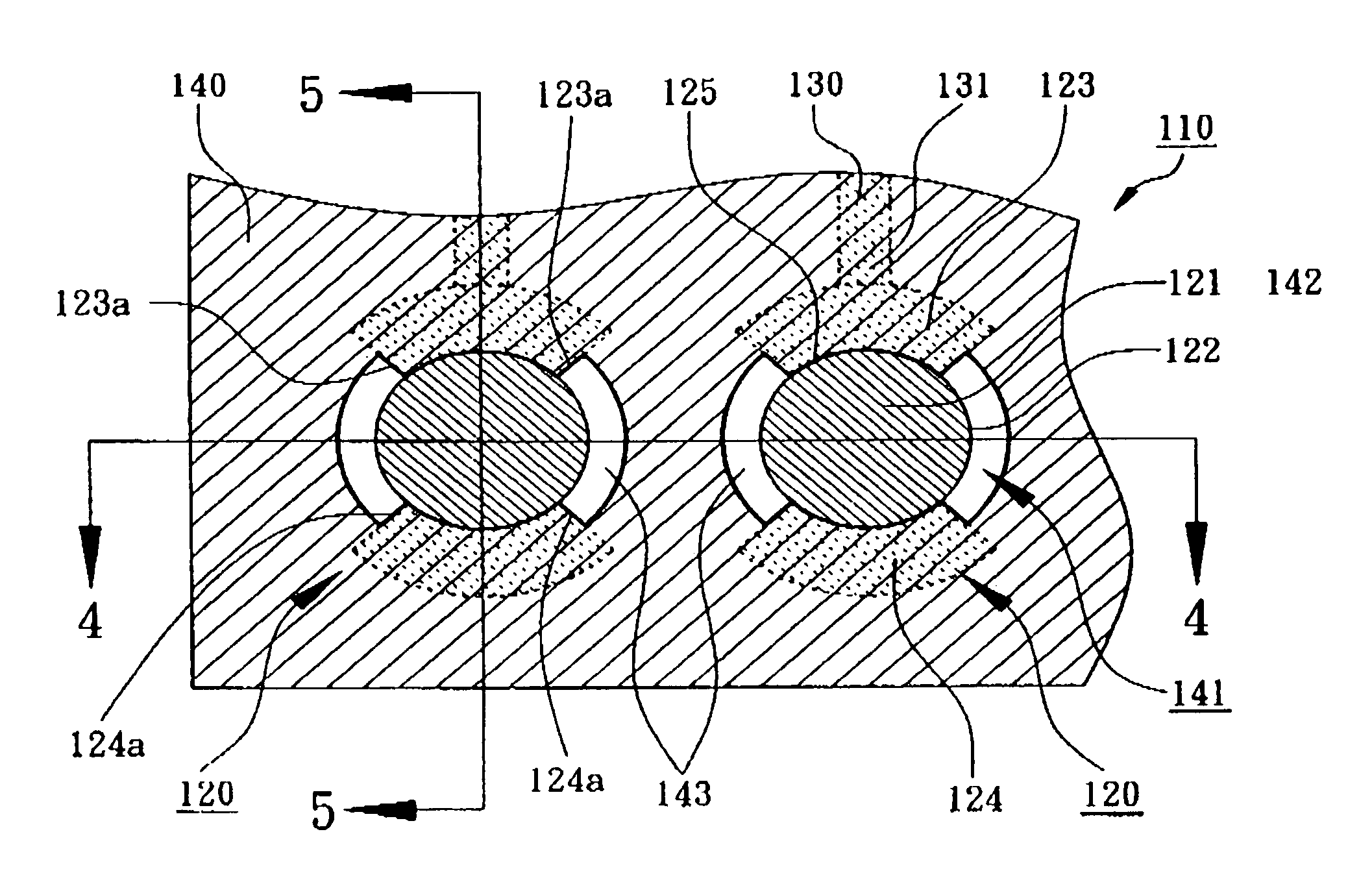
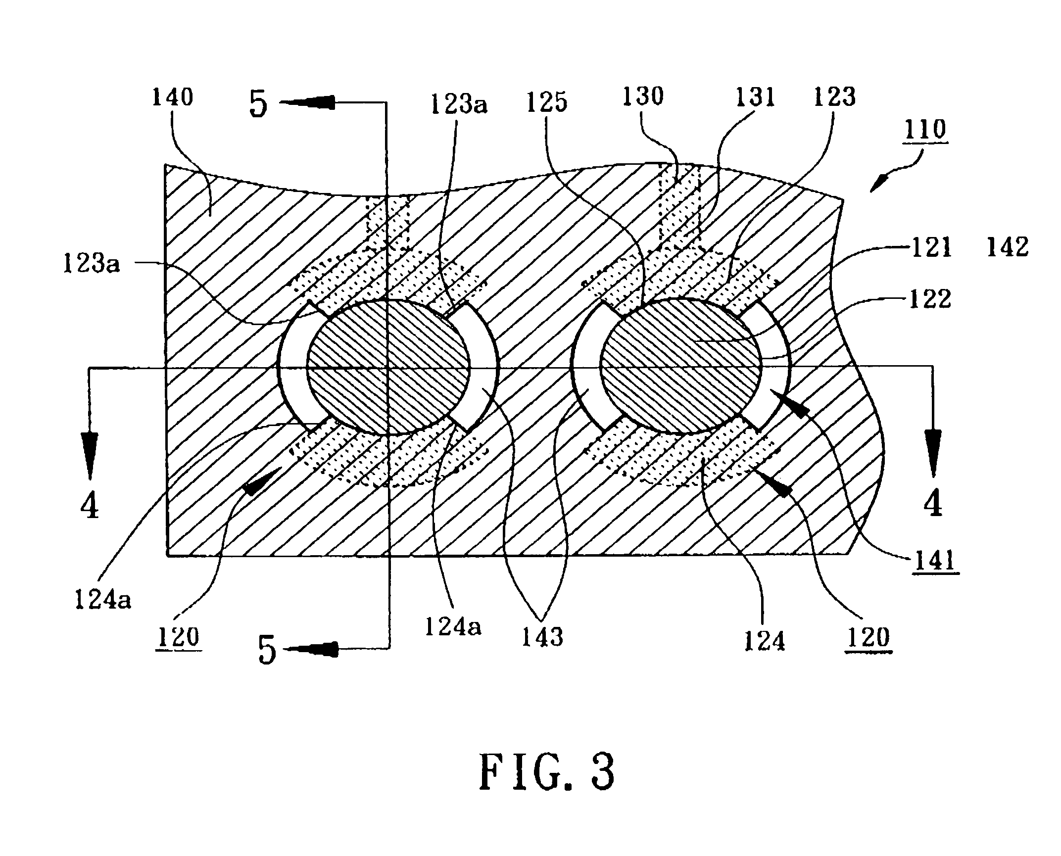
[0014]Please refer to the drawings attached, the present invention will be described by means of an embodiment below. According to an embodiment of the present invention, a substrate with reinforced contact pad structure is shown in FIGS. 3, 4, and 5. It mainly comprises a substrate 110, a metal wiring layer, and a solder mask 140. The metal wiring layer includes at least a contact pad 120, a trace 130, and at least a first extension 123. As shown in FIG. 6, the first extension 123 connects the contact pad 120 and the trace 130. The substrate 110 comprises a resin layer with circuits design, not shown in the figures. The substrate 110 has a surface 111 for SMT connection.

[0015]Referring to FIGS. 4 and 5, the metal wiring layer including the contact pad 120, the trace 130 and first extension 123 is disposed on the surface 111 of the substrate 110. Referring to FIGS. 4 and 6, the contact pad 120 has a bonding surface 121 and a sidewall 122. There is a V-shaped indentation between the ...


PUM


Abstract

A substrate with reinforced contact pad structure includes a metal wiring layer and a solder mask formed over its surface. The metal wiring layer includes at least a NSMD (Non-Solder Mask Defined) type contact pad, a trace and an extension. The extension connects the contact pad and the trace, and has an upper surface which is covered by the solder mask so as to enhance the connecting strength between the trace and the contact pad and to improve the position stability of the NSMD type contact pad on the substrate. In an embodiment, the contact pad is circular for bonding a bump or a solder ball. The first extension is fan-shaped. The extension also has a sidewall exposed out of the solder mask.

Description

FIELD OF THE INVENTION[0001]The present invention relates to a substrate for semiconductor package, more particularly, to a substrate with non-solder mask defined (NSMD) contact pads.BACKGROUND OF THE INVENTION[0002]Conventionally in the substrate with circuit design such as printed circuit boards, flex printed circuit boards, and packaging substrate, contact pads for electrical connection are formed on the surface of these substrates such as aluminum pads or copper pads. By means of bumping, solder ball placement or solder paste printing, contact pads are used for bonding an exterior electrical component, such as flip chip, printed circuit board, or passive component. There are two kinds of contact pads on the substrate, SMD (Solder Mask Defined) and NSMD (Non-Solder Mask Defined), where the dimension of the SMD contact pads are larger than the openings of the solder mask and the dimension of the NSMD contact pads are smaller than the openings of the solder mask, moreover, the edge...

Claims


Application Information

Patent Timeline
Patent Type & Authority Patents(United States)
IPC IPC(8): H01L23/48H01L23/498H05K1/11H05K3/34
CPCH01L23/49811H05K1/111H05K3/3452H05K2201/09381H05K2201/0989H01L2924/0002H05K2201/099H01L2924/00Y02P70/50
Inventor LIU, SHENG-TSUNG
Owner ASE SHANGHAI
Why Eureka
Try Eureka