Impact-resistant film for flat display panel, and flat display panel

a technology for display panels and impact resistance films, which is applied in the direction of gas-filled discharge tubes, discharge tubes/lamp details, synthetic resin layered products, etc., can solve the problems of affecting the weight reduction or thickness reduction of flat display panels, and remarkably deteriorating strength compared with original glass plates. achieve the effects of preventing glass breakage and scattering, weight reduction, and thickness reduction

Inactive Publication Date: 2006-02-28
ASAHI GLASS CO LTD +1
View PDF11 Cites 28 Cited by
  • Summary
  • Abstract
  • Description
  • Claims
  • Application Information

AI Technical Summary

Benefits of technology

[0018]It is an object of the present invention to provide an impact-resistant film for a flat display panel (hereinafter referred to simply as an impact-resistant film) which can be attached to the front surface of the flat display panel to prevent breakage and scattering of glass of the panel upon receipt of an impact and whereby weight reduction and thickness reduction are possible, and to provide a flat display panel employing such a impact-resistant film.
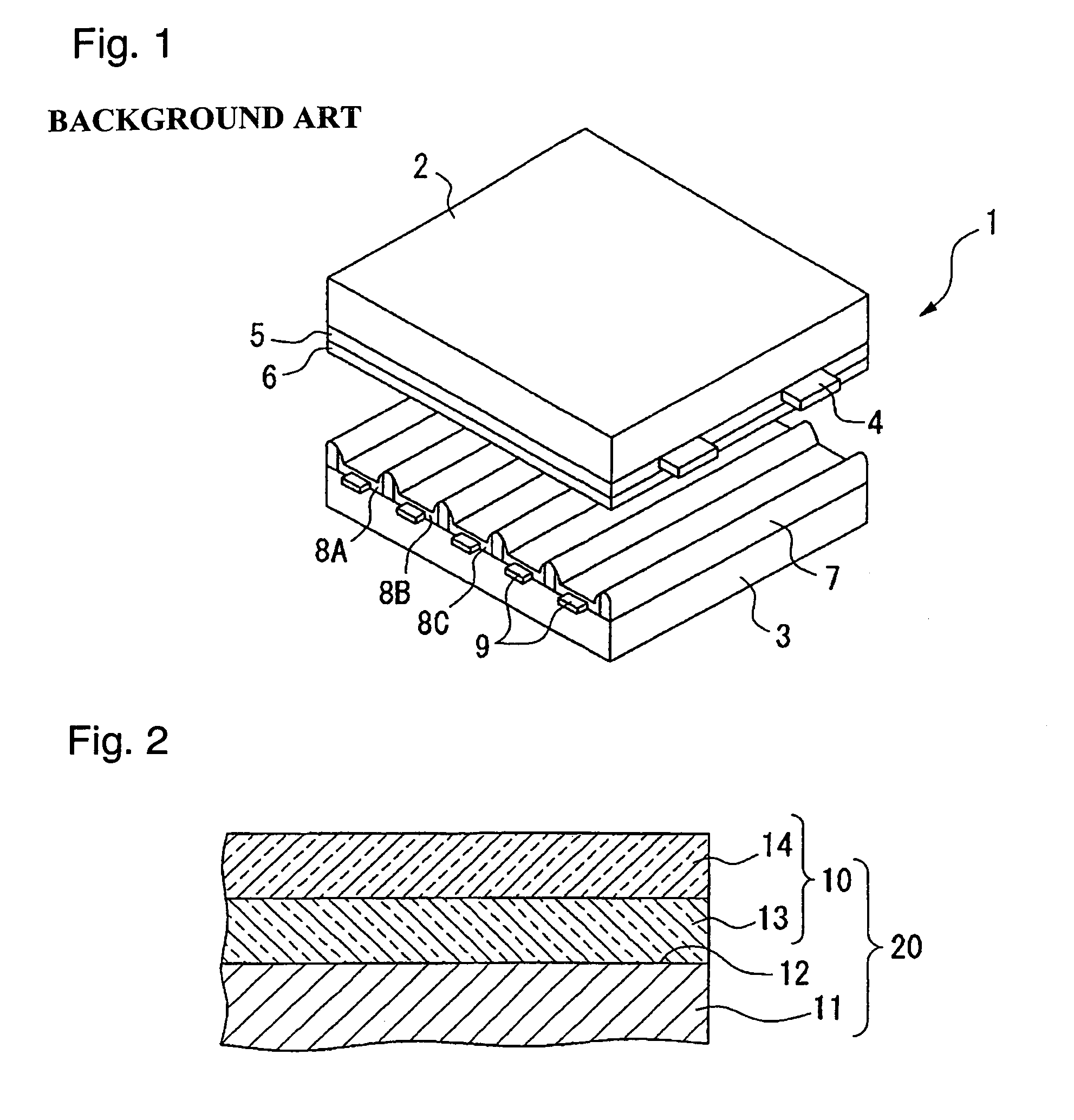
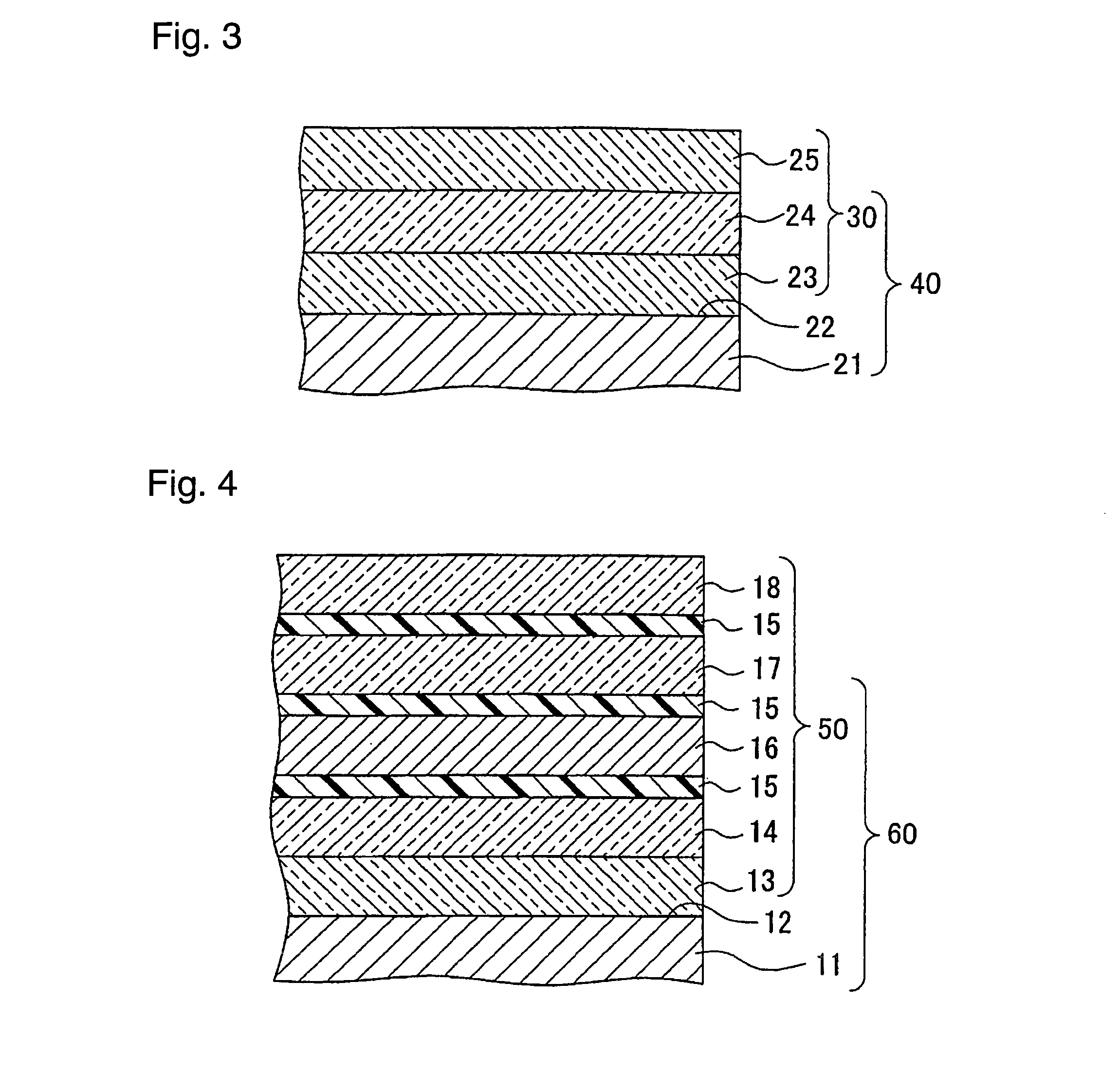
[0020]The impact-resistant film in the first aspect of the present invention is one having the first layer made of a soft transparent synthetic resin having a shear modulus of from 1×10³ Pa to 1×10⁶ Pa and having a thickness within a range of from 1 to 4 mm, provided between the front glass of a flat display panel and the second layer made of a hard transparent synthetic resin having a shear modulus of at least 1×10⁸ Pa and having a thickness within a range of from 0.05 to 3 mm, and upon receipt of an impact, the impact force will be dispersed and absorbed by the second layer and further the impact will be absorbed by the soft first layer provided between the second layer and the front glass, whereby transmission of the impact force to the front glass can be prevented. Thus, it is possible to provide an impact-resistant film which is light in weight, thin and excellent in impact resistance.
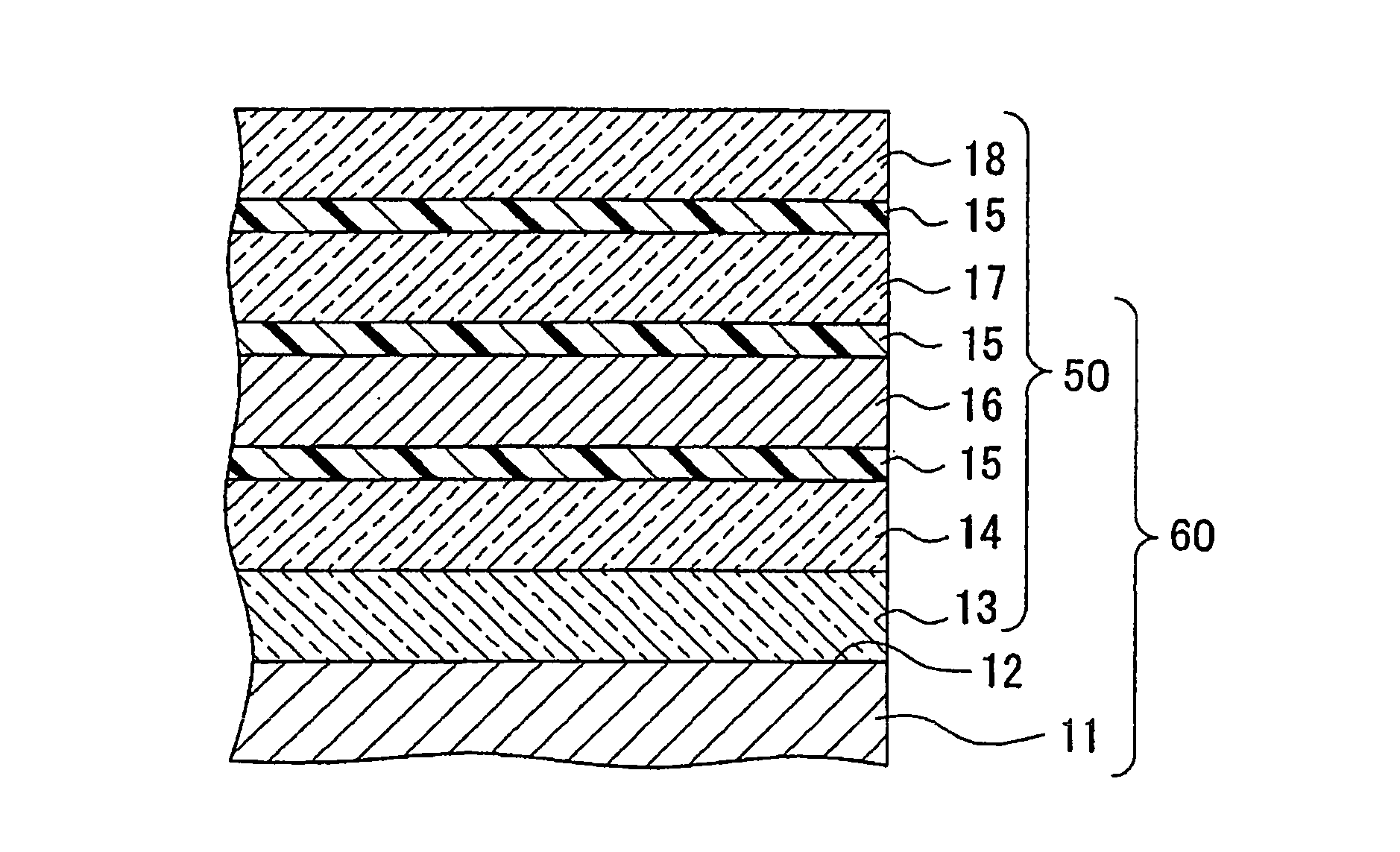
[0024]The impact-resistant film in the second aspect of the present invention has a construction wherein the first layer made of a soft synthetic resin having a shear modulus of from 1×10³ Pa to 1×10⁶ Pa is provided between the front glass of the flat display panel and the second layer made of a hard synthetic resin having a shear modulus of at least 1×10⁸ Pa, and the third layer having a shear modulus of at least 1×10⁶ Pa and less than 1×10⁸ Pa is laminated on the viewer's side of the second layer, and upon receipt of an impact, the impact force will be dispersed and absorbed by the third layer, and further, the impact will be absorbed by the soft first layer provided between the front glass and the second layer, whereby transmission of the impact force to the front glass can be prevented. Thus, it is possible to provide an impact-resistant film which is light in weight, thin and excellent in impact resistance.

Problems solved by technology

The front glass 2 of PDP1 receives scratches or strains at the time of forming or laminating electrodes or thin films made of various materials, and the strength is remarkably deteriorated as compared with the original glass plate.
Further, it is in contact with irregularities of the phosphors or the partition walls formed on the rear glass, and the stress is likely to be concentrated at such contact portions.
However, such a protecting structure has had a problem such that it hinders weight reduction or thickness reduction of the flat display panel.
Further, there is a space between the protecting plate and the front glass of the panel, whereby there has been a problem such that outside light of e.g. a fluorescent lamp is likely to be reflected to deteriorate the image quality, or the screen image is likely to be distorted by slight vibration.
However, with this structure, the protecting effect against impact is inadequate, and it increases the weight of the panel, such being problematic.
However, with this structure, the impact is likely to be transmitted to the front glass, and there has been a problem that no adequate effect to prevent breakage of the front glass can be obtained.
However, such a conventional laminate was inadequate in imparting impact resistance to the front glass of e.g. PDP.
However, as mentioned above, with a real front glass of PDP, as a result of lamination of electrodes or thin films made of various materials, the impact resistance is remarkably deteriorated as compared with non-treated glass and is susceptible to breakage.
Therefore, with such a conventional laminate, it has not been proved that adequate impact resistance can be obtained when bonded to the front glass of PDP, of which the impact resistance is substantially deteriorated as compared with a non-treated glass plate.
Thus, the conventional laminate was inadequate as an impact resistant film to protect the front glass of a flat display panel such as PDP, having the impact resistance deteriorated.

Method used


Image

  • Impact-resistant film for flat display panel, and flat display panel
  • Impact-resistant film for flat display panel, and flat display panel
  • Impact-resistant film for flat display panel, and flat display panel

Examples


example 1

[0087]Preparation of glass substrate: On a high strain glass (PD200, tradename, manufactured by Asahi Glass Company, Limited) having a thickness of 2.8 mm, transparent electrodes, bus electrodes, a transparent dielectric and a protecting film were sequentially laminated to prepare a glass substrate which simulated a front glass of PDP of 950 mm×540 mm. Such respective layers were prepared under the following conditions.

[0088]Transparent electrodes: ITO was formed into a film by a sputtering method, and then an electrode pattern was prepared by photolithography.

[0089]Bus electrodes: Three layers of Cr—Cu—Cr were formed by a sputtering method, and an electrode pattern was prepared by photolithography.

[0090]Transparent dielectric: Paste-like low melting glass was formed into a film by solid printing.

[0091]Protecting film: On the surface of the transparent dielectric, an adhesive (sealing) layer was formed by screen printing, and then MgO was formed into a film by a vapor deposition met...

example 2

[0099]An impact-resistant glass substrate was prepared in the same manner as in Example 1 except that the thickness of the film (first layer) made of the silicone resin in Example 1 was changed to 3.0 mm, and the same tests as in Example 1 were carried out. The results are shown in Table 1.

example 3

[0100]An impact-resistant glass substrate was prepared in the same manner as in Example 1 except that the film (first layer) made of the silicone resin in Example 1 was changed to a film of 2.0 mm in thickness made of a silicone resin (θ-6, tradename, manufactured by GELTEC Co., Ltd.) having a shear modulus of 1.3×10⁵ Pa, and the same tests as in Example 1 were carried out. The results are shown in Table 1.


PUM

PropertyMeasurementUnit
thicknessaaaaaaaaaa
shear modulusaaaaaaaaaa
thicknessaaaaaaaaaa

Abstract

An impact-resistance film which is bondable to a front glass of a flat display panel main body that includes a first layer on the front glass side of the flat display panel that is made of a transparent synthetic resin having a shear modulus of from 1×10³ Pa to 1×10⁶ Pa. The film includes a second layer on the viewer's side of the first layer that is made of a transparent synthetic resin having a shear modulus of at least 1×10⁸ Pa and includes a third layer on the viewer's side of the second layer that is made of a transparent synthetic resin having a shear modulus of at least 1×10⁶ Pa and less than 1×10⁸ Pa.

Description

TECHNICAL FIELD[0001]The present invention relates to an impact-resistant film for a flat display panel, which is to be attached to the front glass of a flat display panel to prevent breakage of the front glass by an impact and at the same time to make the weight reduction and thickness reduction possible, and a flat display panel employing such a film.BACKGROUND ART[0002]In recent years, attention has been drawn to a plasma display panel (hereinafter referred to simply as PDP) which has merits such that a large screen panel can be prepared and clear full color display is possible. PDP is to provide a full color display in such a manner that phosphors are selectively discharged to emit light in a large number of discharge cells isolatedly formed between two glass plates.[0003]FIG. 1 is a view illustrating the structure of PDP. In this FIG., PDP shown by reference numeral 1 has a construction in which a front glass 2 and a rear glass 3 are disposed to face each other, and in the spac...

Claims


Application Information

Patent Timeline
Patent Type & Authority Patents(United States)
IPC IPC(8): H01J1/62H01J63/04B32B7/022B32B7/12B32B17/06B32B17/10B32B27/08B32B27/36B32B27/40C03C17/34G02B1/10H01J5/08
CPCB32B7/02B32B7/12B32B17/06B32B17/10018B32B27/08H01J11/34B32B27/40C03C17/3405G02B1/105H01J5/08B32B27/36B32B2369/00G02B1/14B32B7/022B32B27/00G02B1/11B32B2307/56B32B2307/412B32B2307/212B32B2457/20
Inventor WATANABE, HIROSHIKUMAMOTO, SHIGEMIMIYAKO, TAKEOMIWACHI, HIROSHIMORIWAKI, KEN
Owner ASAHI GLASS CO LTD
Why Eureka
Try Eureka