Cordless power tool system utilizing battery pack connection system with guide rails and guide slots

a cordless power tool and battery pack technology, applied in the field of cordless power tools, can solve problems such as certain disadvantages and limitations

Inactive Publication Date: 2006-02-28
BLACK & DECKER INC
View PDF51 Cites 34 Cited by
  • Summary
  • Abstract
  • Description
  • Claims
  • Application Information

AI Technical Summary

Problems solved by technology

While prior art systems, including but not limited to the type disclosed in U.S. Pat. No. 3,952,239, have proven to be suitable for many intended uses, they are all associated with certain disadvantages and / or limitations.

Method used


Image

  • Cordless power tool system utilizing battery pack connection system with guide rails and guide slots
  • Cordless power tool system utilizing battery pack connection system with guide rails and guide slots
  • Cordless power tool system utilizing battery pack connection system with guide rails and guide slots

Examples


Embodiment Construction

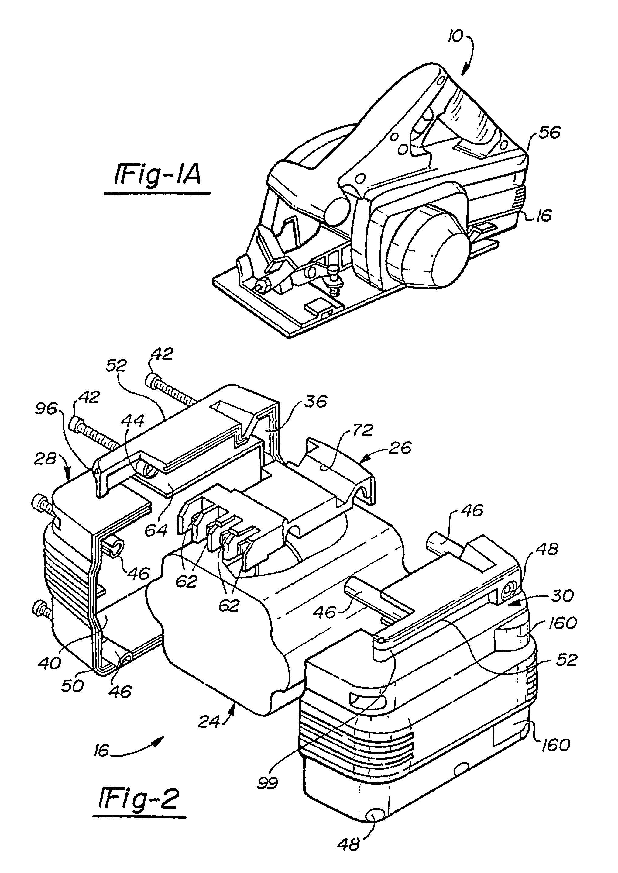
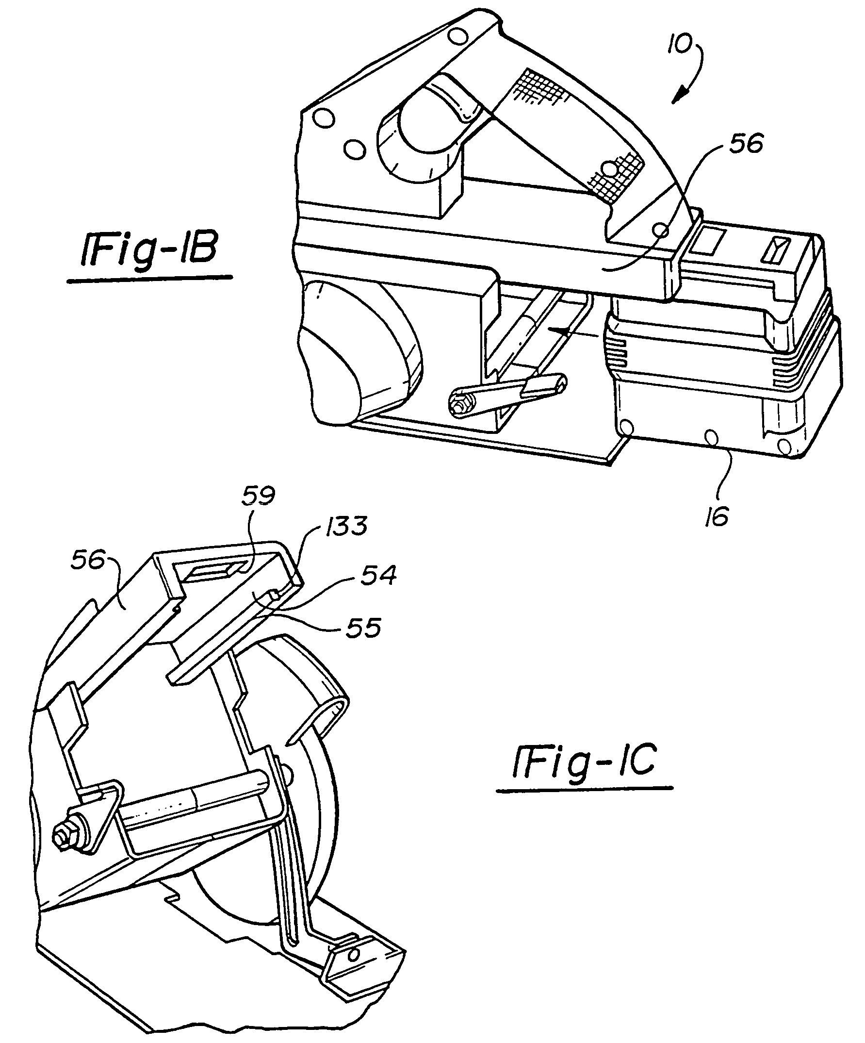
[0039]With general reference to the drawings, a system of cordless power tools constructed in accordance with the teachings of a preferred embodiment of the present invention is illustrated. Exemplary cordless power tools of the system are shown to include, by way of examples, a circular power saw 10 (FIG. 1), a reciprocating saw 12 (FIG. 13), and a drill 14 (FIG. 15). The tools 10–14 each include a conventional DC motor (not shown) adapted to be powered with a common voltage. In the exemplary embodiment, the tools 10–14 are intended to be driven by a 24 volt power source. It will become evident to those skilled that the present invention is not limited to the particular types of tools shown in the drawings nor to specific voltages. In this regard, the teachings of the present invention are applicable to virtually any type of power tool and any supply voltage.

[0040]With continued reference to the drawings, the system of the present invention is additionally shown to generally includ...


PUM

PropertyMeasurementUnit
heightaaaaaaaaaa
widthaaaaaaaaaa
widthaaaaaaaaaa

Abstract

A system of cordless power tools includes a cordless power tool adapted to removably receive a rechargeable battery pack. In each embodiment, the battery pack and the power tool have complementary rails and grooves that aid in aligning the positive and negative blade terminals of the battery pack to the positive and negative tool terminals, respectively, of the power tool. In one embodiment, a keying feature cooperates with a mating keying feature to further align the terminals of the battery pack to the terminals of the power tool. In a second embodiment, the battery pack includes two sets of blade terminals, with each set including a positive blade terminal and a negative blade terminal.

Description

CROSS-REFERENCE TO RELATED APPLICATIONS[0001]This application is a continuation of U.S. patent application Ser. No. 10 / 309,840, filed Dec. 4, 2002, now U.S. Pat. No. 6,653,815 which is a continuation of U.S. patent application Ser. No. 09 / 963,809, filed Sep. 26, 2001 (issued as U.S. Pat. No. 6,515,451), which is a continuation of U.S. Ser. No. 09 / 732,145, filed Dec. 7, 2000 (issued as U.S. Pat. No. 6,304,058), which is a continuation-in-part of U.S. Ser. No. 09 / 579,940, filed May 26, 2000 (issued as U.S. Pat. No. 6,329,788), which is a continuation of U.S. Ser. No. 09 / 133,923, filed Aug. 13, 1998, which is a continuation-in-part of U.S. Ser. No. 09 / 133,924, filed Aug. 13, 1998 (issued as U.S. Pat. No. 6,057,608).FIELD OF THE INVENTION[0002]The present invention generally pertains to power tools. More particular, the present invention pertains to a system of cordless power tools. More specifically, but without restriction to the particular embodiment and / or use which is shown and des...

Claims


Application Information

Patent Timeline
Patent Type & Authority Patents(United States)
IPC IPC(8): H01M10/46B25F5/02B27B9/02H01M50/244H01M50/247H01M50/264H01M50/296H02J7/00
CPCB25F5/02B27B9/02H01M2/10H01M2/1022H02J7/0045H01M2/1066H01M2/30H01M2/34H01M2/1055H01R13/64Y02E60/10H01M50/213Y02P70/50H01M50/264H01M50/247H01M50/296H01M50/244
Inventor WATSON, JAMES B.WHITE, PAUL S.YAHNKER, CHRISTOPHER R.PUZIO, DANIELBODINE, THOMAS J.BRADUS, ROBERTBROTTO, DANIELE C.BUCK, JOHN E.WHITE, DANIEL J.WOODS, SAMUEL G.WALTER, RICHARD T.HARRISON, EDWARD A.AYALA, ADAN
Owner BLACK & DECKER INC
Why Eureka
Try Eureka