Method and apparatus for measuring electric characteristics of cable assembly, and computer product
a technology of electric characteristics and cable assemblies, applied in the direction of resistance/reactance/impedence, line-transmission details, instruments, etc., can solve the problems of synchronization between signals that tend to shift, signal errors tend to occur, and it is difficult to perform the measurement of propagation delay times with a high precision
- Summary
- Abstract
- Description
- Claims
- Application Information
AI Technical Summary
Benefits of technology
Problems solved by technology
Method used
Image

Examples
first embodiment
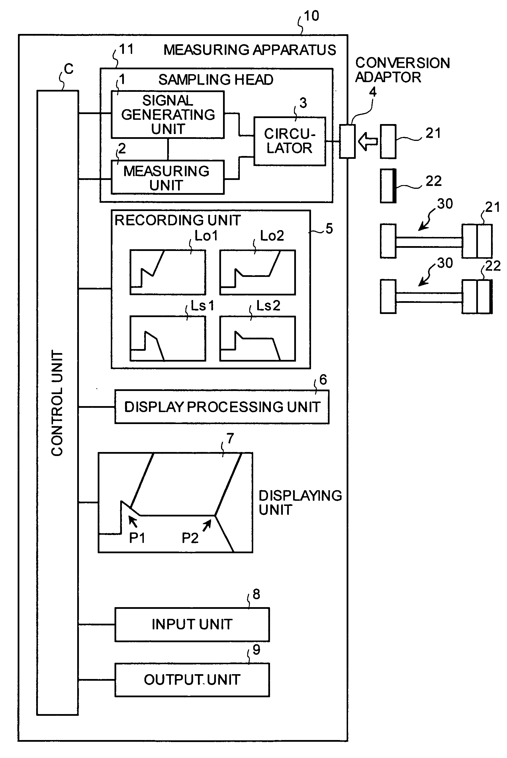
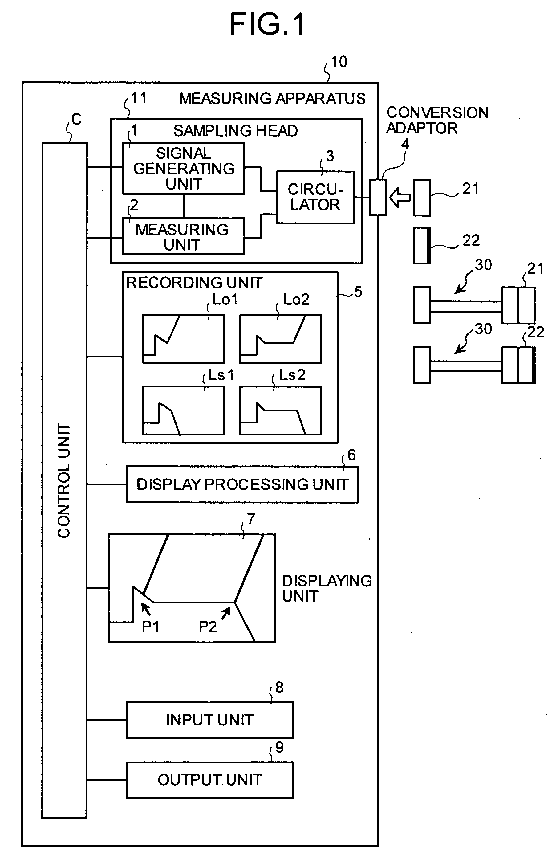
[0044]FIG. 1 is a block diagram of a measuring apparatus according to the present invention. The measuring apparatus, which measures a propagation delay time of a cable assembly 30, includes a sampling head 11, a recording unit 5, and a display processing unit 6, a displaying unit 7, an input unit 8, an output unit 9, and a control unit C that controls these units.
[0045]The sampling head 11 has a signal generating unit 1, a measuring unit 2, and a circulator 3. To perform measurements using high frequency signals, the sampling head is carried to near the cable assembly and is connected to the body of a measuring apparatus 10. This high-frequency measurements with high precision while minimizing influences of cable length and so on. The signal generating unit 1 generates high frequency signals that the cable assembly 30 transmits. The signals are sent to the side of the cable assembly 30 through the circulator 3. The high frequency signals that reflect from the side of the cable asse...
second embodiment
[0075]FIG. 16 is a block diagram of the measuring apparatus according to the A measuring apparatus 60 includes a propagation-delay-time calculating unit 61 in addition to the configuration of the measuring apparatus 10 shown in FIG. 1. The other configurations are the same as those of the measuring apparatus 10 and the same parts or components are indicated by the same reference numerals.
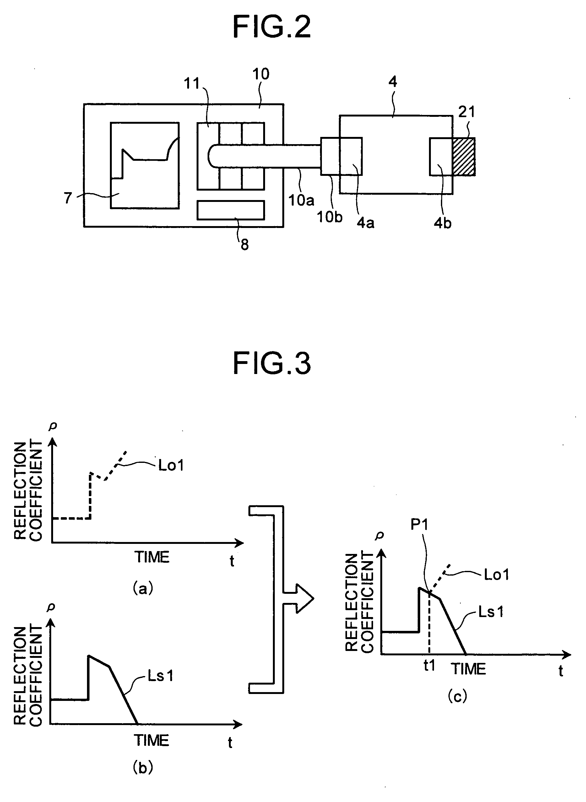
[0076]When the time-dependent variations of the amplitude of reflection coefficient are displayed in superposition on the displaying unit 7 and the branch points P1 and P2 are pointed by, for example, a pointer, the propagation-delay-time calculating unit 61 obtains time t1 and t2 that correspond to the positions pointed, and obtains a half of the difference in time between t1 and t2 as a propagation delay time Td. The obtained propagation delay time Td is displayed in a display region 7a of the displaying unit 7.
[0077]Referring to the flowchart shown in FIG. 17, the procedure of measurement using ...
third embodiment
[0083]According to the present invention, the branch points P1 and P2 are automatically obtained and propagation delay times are automatically obtained and displayed on the displaying unit 7.
[0084]FIG. 18 is a block diagram of the measuring apparatus according to the third embodiment. A measuring unit 70 includes a branch point detecting unit 71 in addition to the configuration of the measuring apparatus 60. Other configurations are the same as those of the measuring apparatus 60 shown in FIG. 16. The same parts or components are designated by the same reference numerals.
[0085]The branch point detecting unit 71 performs calculations for obtaining the two time-dependent variations of the amplitude of reflection coefficient at the branch points P1 and P2, respectively. The positions of the obtained branch position P1 and P2 are input to the propagation-delay-time calculating unit 61, which obtains the time t1 and t2 at the branch points P1 and P2, respectively, and a half of the diffe...
PUM
 Abstract
Description
Claims
Application Information
 - R&D
- Intellectual Property
- Life Sciences
- Materials
- Tech Scout
- Unparalleled Data Quality
- Higher Quality Content
- 60% Fewer Hallucinations
Browse by: Latest US Patents, China's latest patents, Technical Efficacy Thesaurus, Application Domain, Technology Topic, Popular Technical Reports.
© 2025 PatSnap. All rights reserved.Legal|Privacy policy|Modern Slavery Act Transparency Statement|Sitemap|About US| Contact US: help@patsnap.com