
Method and apparatus for describing solid shapes, and CAD/CAM system which employs the method

a solid shape and apparatus technology, applied in the field of methods and apparatus for describing solid shapes, can solve the problems of data not being accurate geometrically, defects a and c, but still remain unsolved problems, and each of the above-described methods has merits and defects

Inactive Publication Date: 2006-02-28
HITACHI LTD
View PDF11 Cites 17 Cited by
  • Summary
  • Abstract
  • Description
  • Claims
  • Application Information

AI Technical Summary

Benefits of technology

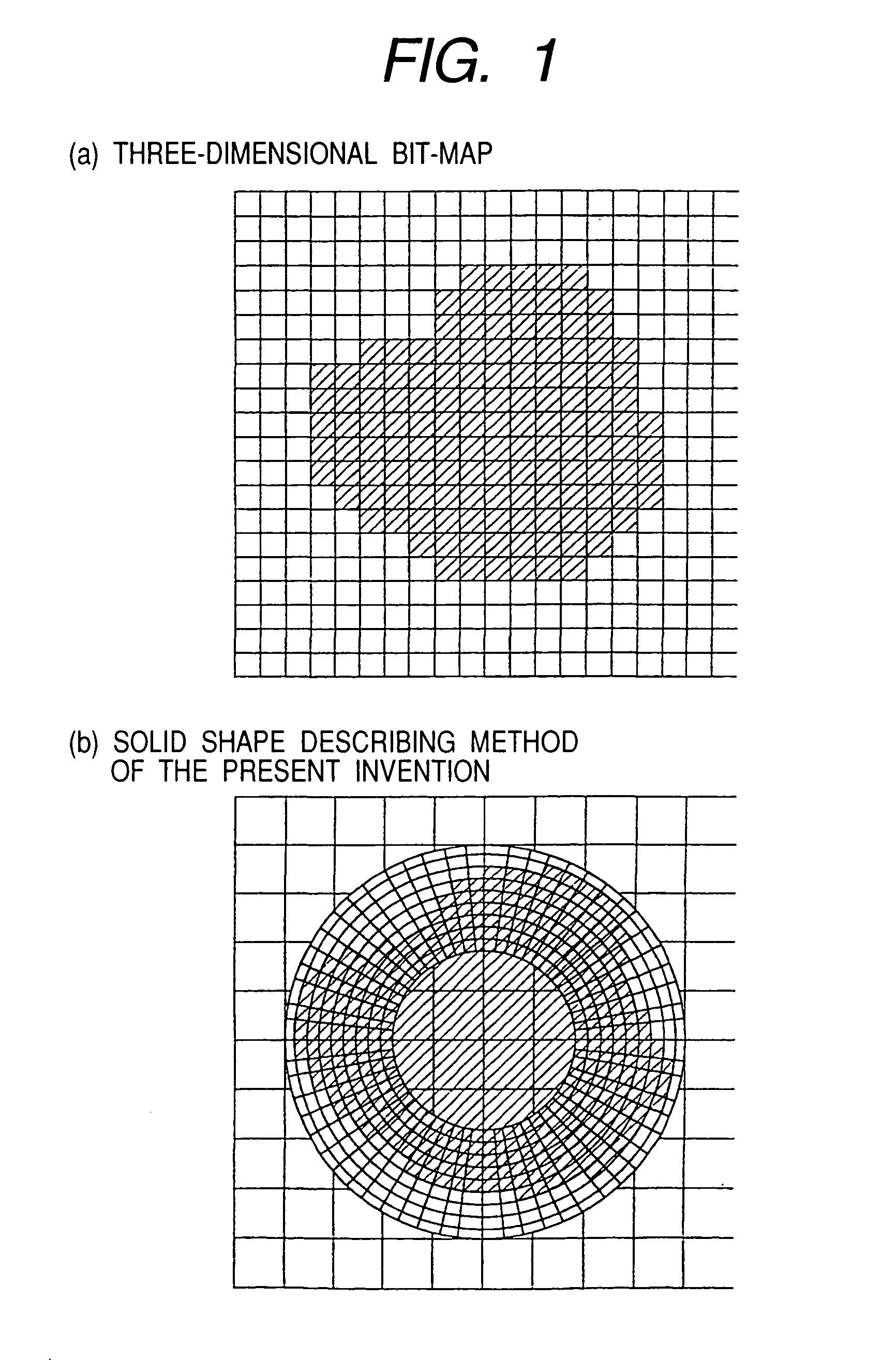
[0030]Under such circumstances, it is an object of the present invention to provide a solid shape describing method for describing solid models, which can reduce the solid shape data size and make each solid shape data include feature-related information while the merits of the three-dimensional bit-map, as well as an engineering system which employs the method. The above-described features of the three-dimensional bit-map are, for example, that the same data is always assumed for the same shape, the same data structure is kept at slight deformation, the data size is prevented from limitless increasing even for a complicated model.

Problems solved by technology

Each of the above-described methods have merits and defects.
Data is not so accurate geometrically.
The defects a and c, however, have still remained as unsolved problems.
This makes it difficult to use the solid model.
Improvement of the compression rate has been difficult so far.
To provide a solid shape with feature-related information, for example, geometrical characteristics, as well as meaning, machining method, and accuracy of the solid shape, a method for adding solid shape data described using the B-reps and CSG methods to the subject solid shape has been used sometimes. This method, however, increases the data size and almost lose the merits e, f, and g of the 3-dimensional bit-map.
Any of the above conventional techniques, therefore, have not so effective to solve the defects of the 3-dimensional bit-map while the merits thereof are kept as are.

Method used


Image

  • Method and apparatus for describing solid shapes, and CAD/CAM system which employs the method
  • Method and apparatus for describing solid shapes, and CAD/CAM system which employs the method
  • Method and apparatus for describing solid shapes, and CAD/CAM system which employs the method

Examples


first embodiment

(First Embodiment)

[0127]FIG. 7 shows a block diagram of a remote solid machining apparatus SA in the first embodiment of the present invention. The system SA includes a three-dimensional CAD apparatus S1 and a three-dimensional machining apparatus S2 that are connected to each other through a communication line S33.

[0128]The three-dimensional CAD apparatus S1 includes a shape processor S11, a data storage unit S12, a display unit S13, an operator console S14, and an external interface S15.

[0129]The shape processor S11 may be a personal computer or work station provided with a CPU, a memory, and programs and data stored in the memory. The shape processor S11, when receiving a command D2 from the operator console S14, executes the corresponding processing, such as creation, modification, correction, and comparison of the solid shape data D stored in the data storage unit S12, as well as such processing as changes of the data structure and inputs / outputs of data.

[0130]The data storage ...

second embodiment

(Second Embodiment)

[0152]FIG. 14 shows a block diagram of a solid shape CAD / CAM system SB in the second embodiment of the present invention. The solid shape CAD / CAM system SB includes a three-dimensional CAD apparatus 1, an optical fabrication unit S4, and an X-ray CT unit S5. The optical fabrication unit S4 and the X-ray CT unit S5 are connected to the three-dimensional CAD apparatus S1 respectively.

[0153]The three-dimensional CAD apparatus S1 is the same as that in the first embodiment.

[0154]The optical fabrication unit S4, when receiving a modeling data D4 described by the solid shape describing method of the present invention from the three-dimensional CAD apparatus S1, manufactures a real body having the solid shape with resin, etc. For the details of the optical fabrication technique, which is an operation principle of the optical modeling unit S4, refer to “Laminated Modeling System (Takeo Nakagawa, Yoji Marutani / KOGYO CHOSAKAI PUBLISHING CO., LTD.)

[0155]The X-ray CT unit S5 ...

third embodiment

(Third Embodiment)

[0187]Next, a description will be made for the effects to be obtained by the solid shape CAD / CAM system SB of the present invention for designing a shape of a railway vehicle as the third embodiment of the present invention. FIG. 17 shows the original shape data D5 of the railway vehicle described by the solid shape describing method of the present invention. These original shape data D5 are created as a simple rectangular body using a three-dimensional CAD apparatus.

[0188]The following shapes must be determined in prior to the designing of the railway vehicle.

[0189]1. The shape of the front portion (where the driver's seat exists)

[0190]2. The shape of the rear external periphery (outer periphery of a passenger car)

[0191]Some coordinate systems are thus defined for the original solid shape data D5. At first, each floating coordinate system DF is defined so that its grid has a higher resolution than that of the fixed coordinate system DA. Then, a floating coordinate...


PUM


Abstract

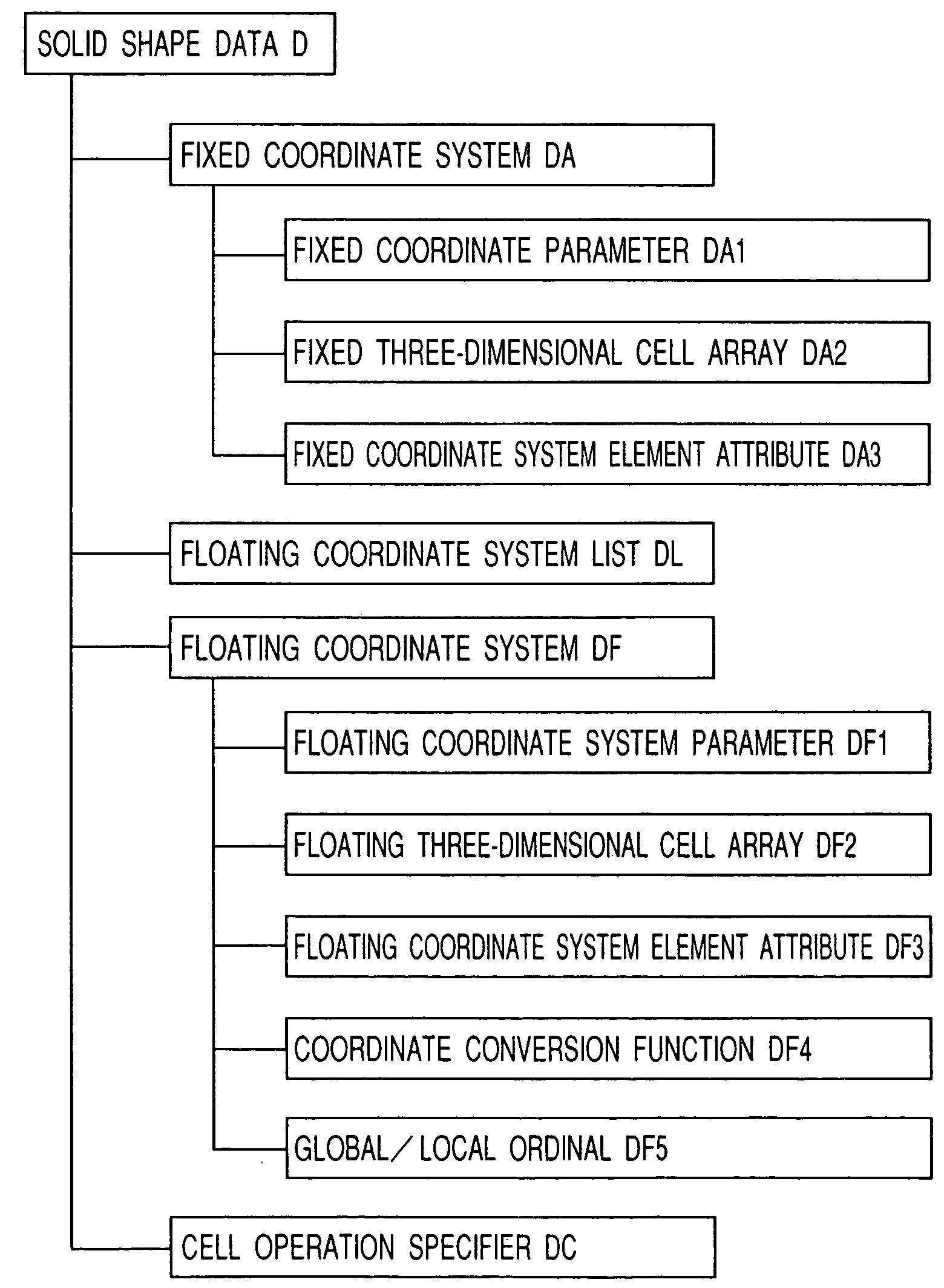
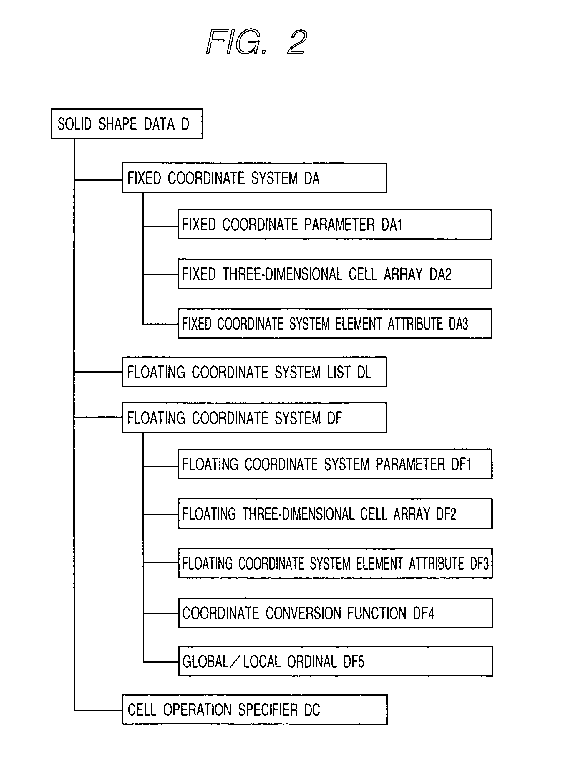
Disclosed is a solid shape describing apparatus provided with a function for defining both absolute coordinate system and floating coordinate system, a function for describing a relationship between the absolute coordinate system and the floating coordinate system, a function for defining a three-dimensional cell array, a function for describing the correspondence between the floating coordinate system and the three-dimensional cell array, and a function for converting the three-dimensional cell array to a solid model.

Description

[0001]This application is a continuation of application Ser. No. 10 / 239,058 filed Sep. 19, 2002 now U.S. Pat. No. 6,982,711, which is a 371 of PCT / JP00 / 06366, filed Sep. 18, 2000.TECHNICAL FIELD[0002]The present invention relates to a method and an apparatus for describing solid shapes and a CAD / CAM system which employs the method. More particularly, the present invention relates to a method and an apparatus for describing solid shapes preferred to describe, operate, and send free solid shapes, as well as a CAD / CAM system that employs the method.BACKGROUND ART[0003]There are many well-known solid shape data items used to describe solid shapes. “Solid model” and “surface model” among them are used most frequently. The “solid model” means solid shape data structured so that, when a solid body and a point are given, which of the inside, outside, and surface of the solid body includes the point can be determined by a certain procedure. On the other hand, the “surface model” does not hav...

Claims


Application Information

Patent Timeline
Patent Type & Authority Patents(United States)
IPC IPC(8): G06T15/00G06F17/50G05B19/4097G06T17/10G06T17/20
CPCG06T17/10G06T17/20G06T2210/32
Inventor TAKAGI, TAROU
Owner HITACHI LTD
Learn More