
Transmitter, receiver and transmitting method in multi-carrier transmission system

a transmission system and multi-carrier technology, applied in the field of multi-carrier transmission system, can solve the problems of high amplifier price, increased peak power (or peak-to-average power ratio) of transmitting signal, and frequency-selective fading due to multi-path degrading circuit quality

Inactive Publication Date: 2006-02-28
FUJITSU LTD
View PDF13 Cites 30 Cited by
  • Summary
  • Abstract
  • Description
  • Claims
  • Application Information

AI Technical Summary

Benefits of technology

[0028]The present invention having the configuration described above provides both a transmitter with an encoder implementing a high encoding rate of ⅞ while suppressing peak power to approximately 2 dB and a receiver decoding the transmitted signals by the transmitter.

Problems solved by technology

In broadband wireless communications, frequency-selective fading due to multi-path degrading circuit quality is especially problematic.
One of the problems of the multi-carrier technology is the increase of the peak power (or peak-to-average power ratio) of a transmitting signal.
However, this amplifier is expensive and the power efficiency is low.
If a cheap amplifier is used, non-linear distortion is caused by using a saturation region, and the characteristic degrades, which is a problem.
For this reason, the technology cannot be put into practical use yet.
This technology increases a side-lobe level due to non-linear distortion, that is, it causes inter-carrier interference.
Thus, the latter method degrades the characteristic.
Therefore, the method also degrades the characteristic.
Since the encoding rate decreases in proportion to the number of sub-carriers, the reduction of transmission efficiency cannot be avoided even if the improvement of error correction capability is taken into consideration.
However, even in this case, R≦¾ and the encoding rate cannot be further increased.
Therefore, the encoding technology is not suited for high-speed signal processing, which is a problem.

Method used


Image

  • Transmitter, receiver and transmitting method in multi-carrier transmission system
  • Transmitter, receiver and transmitting method in multi-carrier transmission system
  • Transmitter, receiver and transmitting method in multi-carrier transmission system

Examples


Embodiment Construction

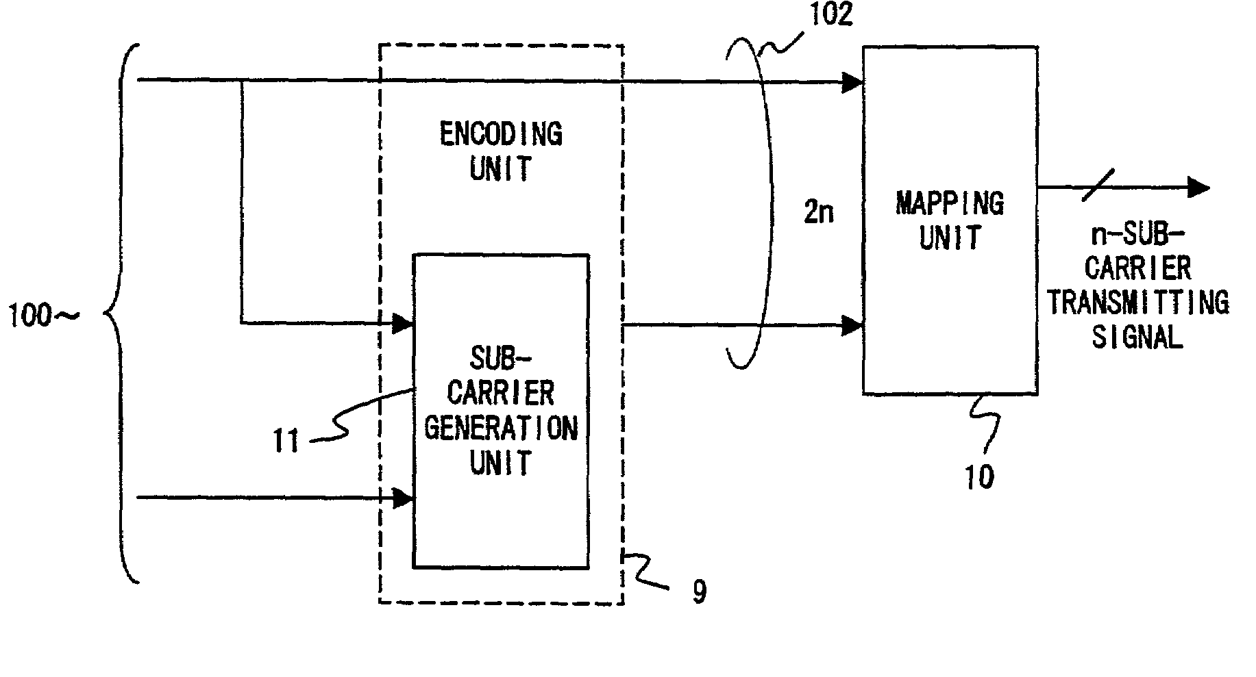
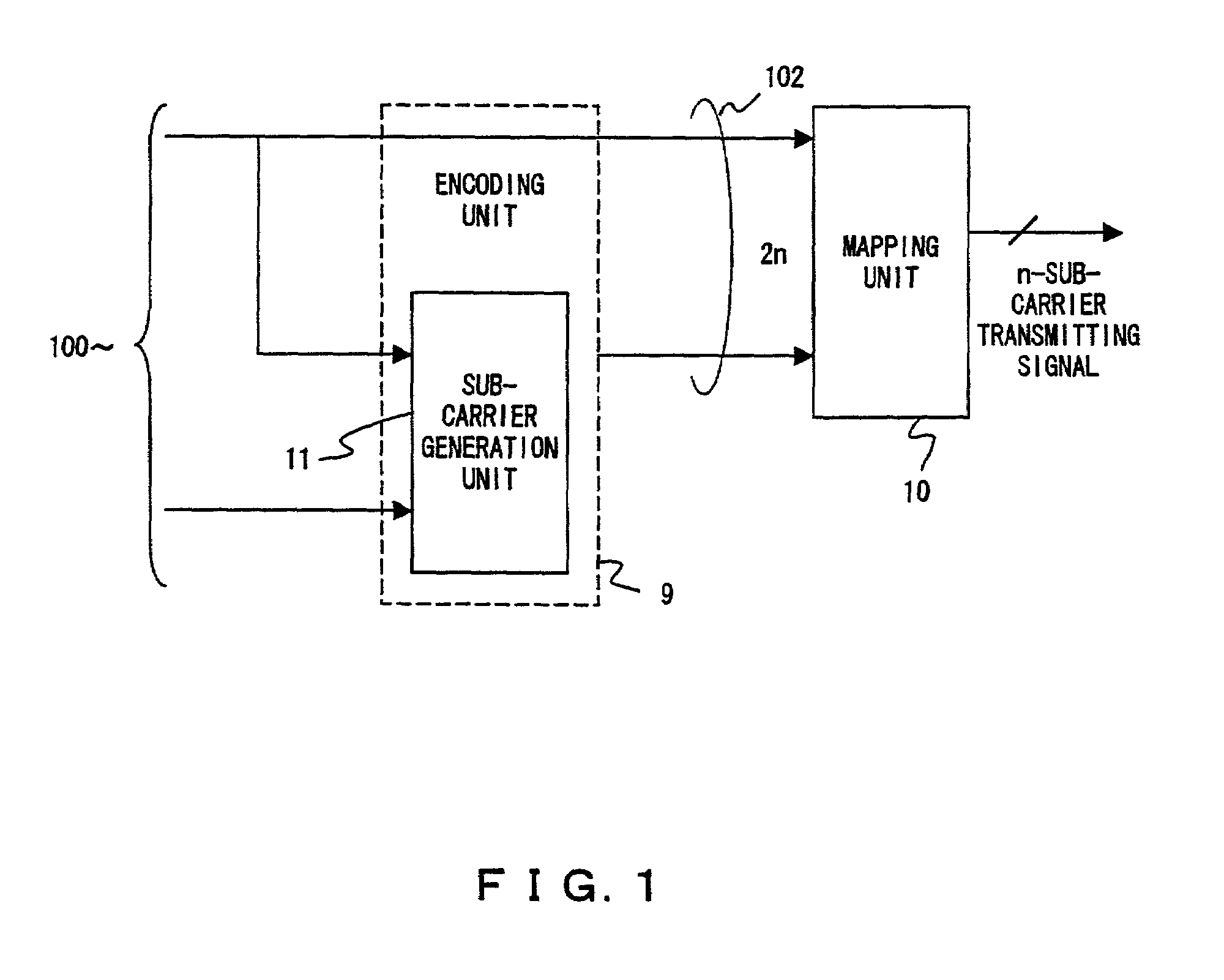
[0052]The present invention adopts a peak power suppression encoding system for preventing a signal point pattern, the peak power of which is increased by an encoding process, from occurring in order to suppress the peak power of a transmitting signal. The principle of the present invention is described with reference to FIG. 1.

[0053]The present invention provides a transmitter in a multi-carrier transmission system for conducting communications using a QPSK modulation system in which a transmission band is divided into a plurality of sub-carriers and, for example, each carrier is mapped by a complex signal point expressed by two bits. The system comprises an encoding unit converting transmission data information of the number of bits less than 2n bits, which are data for expressing n sub-carriers, into a signal point pattern with the small peak power of a transmitting signal of signal point patterns expressed by the 2n bits, the encoding unit further comprising a sub-carrier genera...


PUM


Abstract

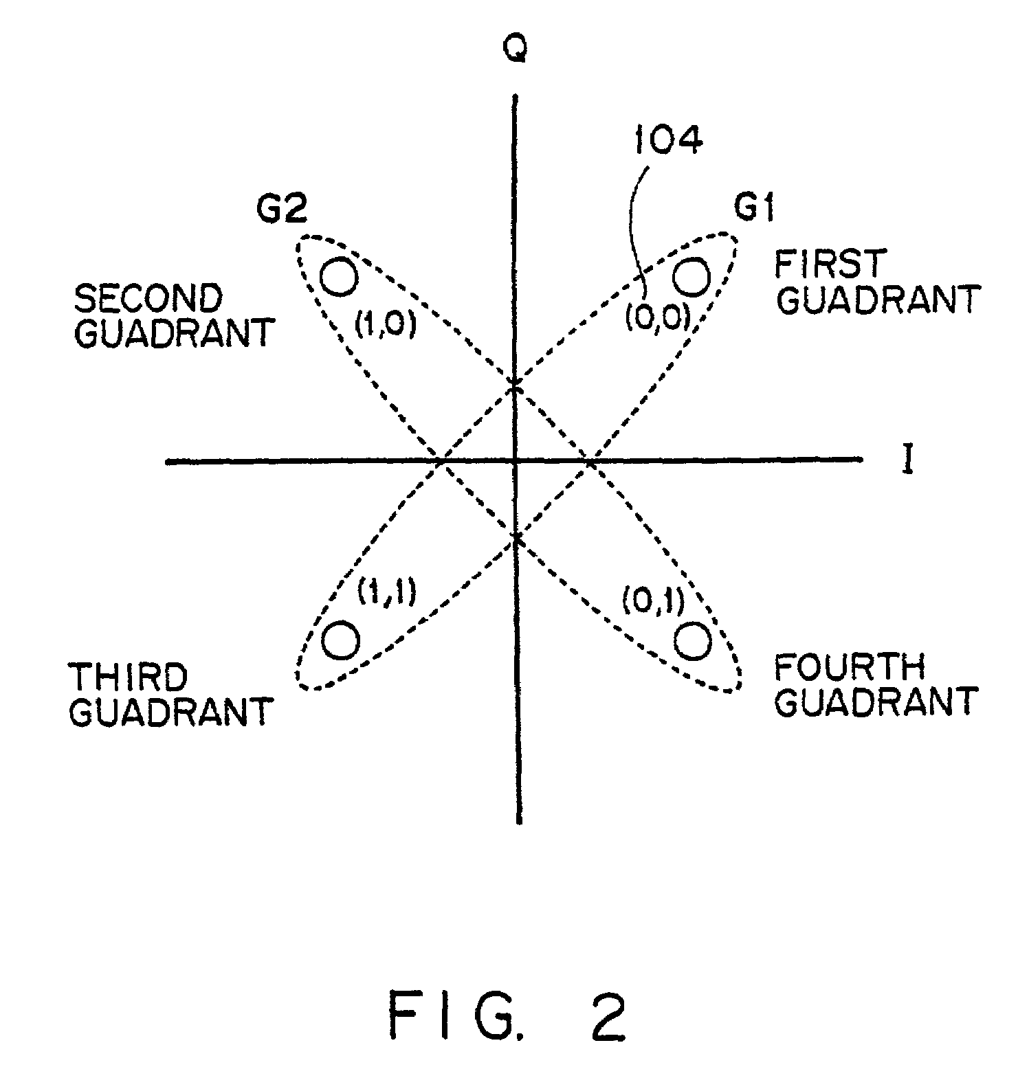
An object of the present invention is to provide a method for suppressing peak power at a high encoding rate in a multi-carrier transmission system.The present invention provides a transmitter for transmitting a multi-carrier signal, in which when generating 128 patterns used to suppress the peak power of 8-bit sub-carrier mapping signals from 7-bit information bits in a encoding unit 9, a sub-carrier generation unit 11, for example, divides the signal point of QPSK modulation into orthogonal groups, generates a sub-carrier mapping signal in which a part of sub-carriers is dependent on the signal point of another sub-carrier and a receiver for receiving such a multi-carrier signal.

Description

CROSS REFERENCE TO RELATED APPLICATION[0001]This application is a continuation of international PCT application No. PCT / JP99 / 05390 filed on Sep. 30, 1999.BACKGROUND OF THE INVENTION[0002]1. Field of the Invention[0003]The present invention relates to a multi-carrier transmission system for conducting communications by dividing a transmission band into a plurality of sub-carriers and is one of several broadband wireless communications systems, and more specifically, relates to a transmitter, a receiver and a transmitting method for encoding in such a way that the peak power of a transmitting signal can be suppressed in a multi-carrier transmission system for conducting communications by a QPSK-modulation method for mapping each sub-carrier using a complex signal point expressed by two bits.[0004]2. Description of the Related Art[0005]In broadband wireless communications, frequency-selective fading due to multi-path degrading circuit quality is especially problematic. As a modulation ...

Claims


Application Information

Patent Timeline
Patent Type & Authority Patents(United States)
IPC IPC(8): H04L12/28H04B7/208H04K1/10H04L27/28H04L27/26
CPCH04L27/2615
Inventor YOSHIDA, MAKOTOISHIZU, EIZOU
Owner FUJITSU LTD
Learn More