Radiographic apparatus

a technology of radiographic equipment and x-ray images, which is applied in the field of radiographic equipment, can solve the problems of time lags whose adverse influence appears in x-ray images, blurred dynamic images, and inability to avoid artifacts, and achieve the effect of removing time lags

Inactive Publication Date: 2006-02-28
SHIMADZU CORP
View PDF6 Cites 13 Cited by
  • Summary
  • Abstract
  • Description
  • Claims
  • Application Information

AI Technical Summary

Benefits of technology

[0016]This invention has been made having regard to the state of the art noted above, and its object is to provide a radiographic apparatus for fully eliminating time lags, due to a radiation detecting device, of radiation detection signals taken from the radiation detecting device.

Problems solved by technology

However, the FPD has a drawback of causing time lags whose adverse influence appears in X-ray images.
This results in an inconvenience such as blurring of dynamic images.
However, the only result obtained is that the above technique cannot avoid artifacts due to the time lag and satisfactory X-ray images cannot be obtained.
It has been found, however, that it is impossible for one exponential function to approximate the time lag of the FPD, and the time lag is not eliminated by this technique, either.

Method used


Image

  • Radiographic apparatus
  • Radiographic apparatus
  • Radiographic apparatus

Examples


first embodiment

[0075

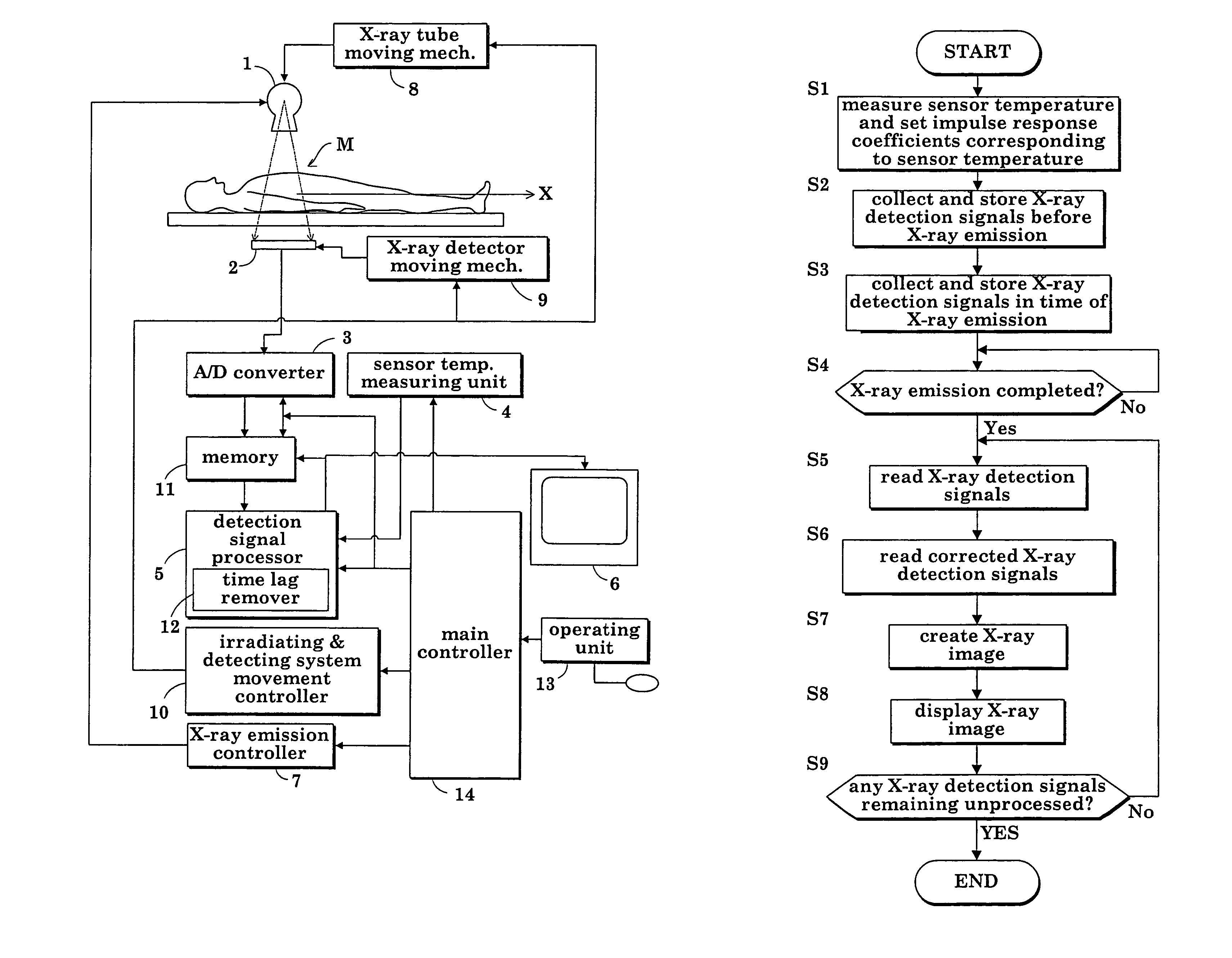
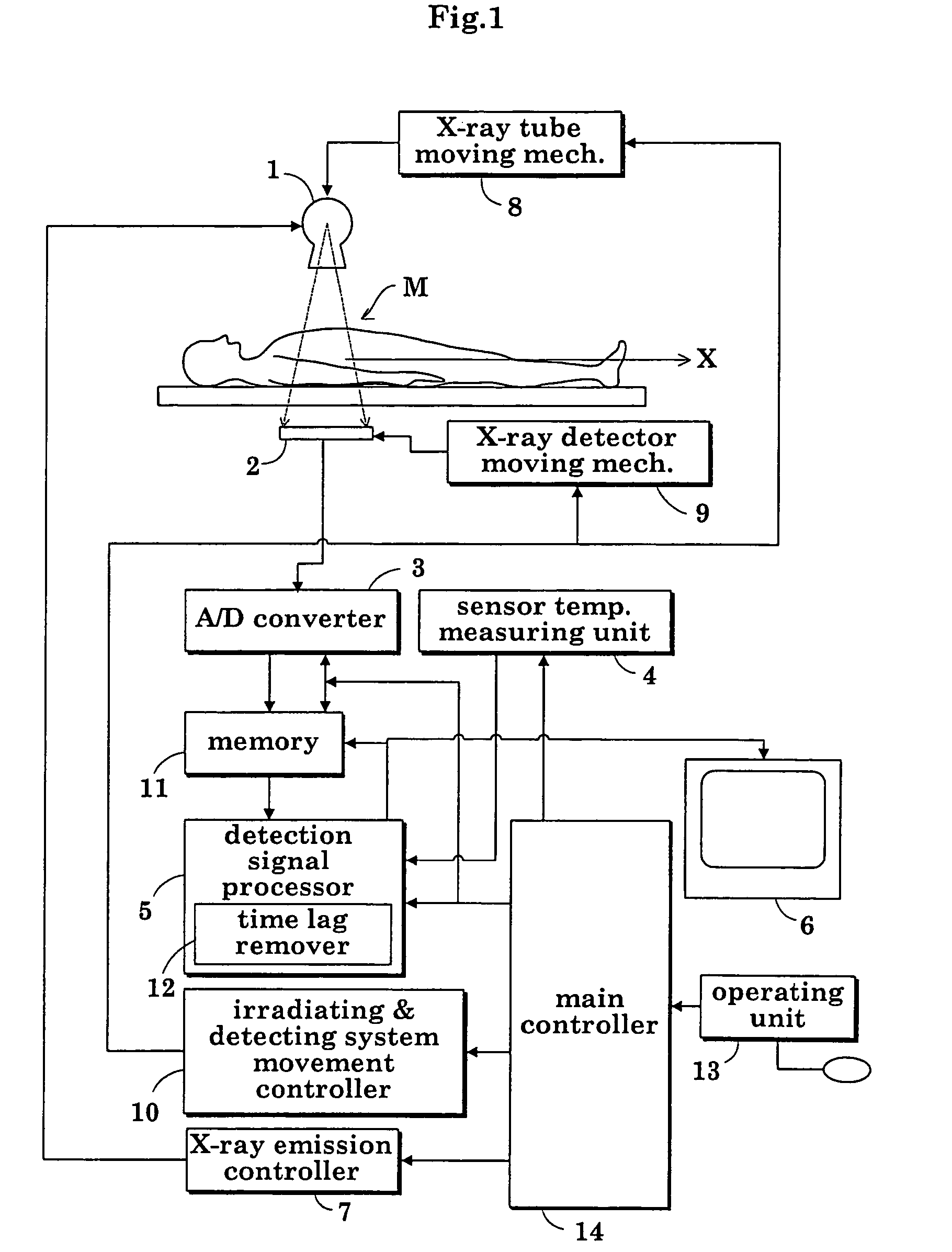
[0076]FIG. 1 is a block diagram showing an overall construction of a fluoroscopic apparatus in a first embodiment.

[0077]As shown in FIG. 1, the fluoroscopic apparatus includes an X-ray tube (radiation emitting device) 1 for emitting X rays toward a patient M, an FPD (radiation detecting device) 2 for detecting X rays transmitted through the patient M, an analog-to-digital converter (signal sampling device) 3 for digitizing X-ray detection signals (radiation detection signals) taken from the FPD (flat panel X-ray detector) 2 at predetermined sampling time intervals Δt, a sensor temperature measuring unit (temperature measuring device) 4 for measuring a sensor temperature of FPD 2, a detection signal processor 5 for creating X-ray images based on X-ray detection signals outputted from the analog-to-digital converter 3 and measurements provided by the sensor temperature measuring unit 4, and an image monitor 6 for displaying the X-ray images created by the detection signal process...

second embodiment

[0126

[0127]In the second embodiment, the sensor temperature is measured automatically at every predetermined time.

[0128]The second embodiment has the same features and functions as the first embodiment except that the sensor temperature is measured on instructions from the operator or at predetermined times. What is common with the first embodiment will not be described, but only the different aspects will be described by using FIG. 9.

[0129]FIG. 9 is a flow chart showing an operation for setting a sensor temperature measurement and impulse response coefficients according to sensor temperatures in the second embodiment.

[0130][Step P1] The operator inputs points of time for performing a sensor temperature measurement through the sensor temperature measuring unit 4, operating unit 13 and main controller 14.

[0131][Step P2] The controller 26 of the sensor temperature measuring unit 4 checks whether a predetermined time has arrived.

[0132][Step P3] At the predetermined time, the controller...


PUM


Abstract

A radiographic apparatus removes lag-behind parts from radiation detection signals taken from an FPD as X rays are emitted from an X-ray tube, on an assumption that the lag-behind part included in each X-ray detection signal is due to an impulse response formed of exponential functions, N in number, with different attenuation time constants. The lag-behind parts are removed by using impulse responses corresponding to variations in the sensor temperature of the FPD. X-ray images are created from corrected radiation detection signals with the lag-behind parts removed therefrom.

Description

BACKGROUND OF THE INVENTION[0001](1) Field of the Invention[0002]This invention relates to a radiographic apparatus for medical or industrial use, for obtaining radiographic images based on radiation detection signals fetched at predetermined sampling time intervals by a signal sampling device from a radiation detecting device as radiation is emitted from a radiation emitting device. More particularly, the invention relates to a technique for fully eliminating time lags, due to the radiation detecting device, of the radiation detection signals taken from the radiation detecting device.[0003](2) Description of the Related Art[0004]In a medical fluoroscopic apparatus which is a typical example of radiographic apparatus, a flat panel X-ray detector (hereinafter called “FPD” as appropriate) has recently been used as an X-ray detecting device for detecting X-ray penetration images of a patient resulting from X-ray emission from an X-ray tube. The FPD includes numerous semiconductor or ot...

Claims


Application Information

Patent Timeline
Patent Type & Authority Patents(United States)
IPC IPC(8): H05G1/64G01T1/00A61B6/00G01T1/17G01T1/24G21K5/10H01L27/14H04N5/32H04N5/357H04N5/378
CPCA61B6/00A61B6/4233H04N5/3597H04N5/325H04N5/32H04N25/626
Inventor OKAMURA, SHOICHIYOSHIMUTA, TOSHINORI
Owner SHIMADZU CORP
Why Eureka
Try Eureka