Method and apparatus for correcting crosstalk and spatial resolution for multichannel imaging

a multi-channel imaging and spatial resolution technology, applied in the field of multi-channel imaging methods and equipment, can solve the problems of preventing the accurate estimation of the intensity of the signal from each dye, interference can be introduced into a channel dedicated to a first signal, and information can be degraded during the capture process, so as to reduce the contribution of erroneous information

Inactive Publication Date: 2006-02-28
CYTEK BIOSCI
View PDF61 Cites 72 Cited by
  • Summary
  • Abstract
  • Description
  • Claims
  • Application Information

AI Technical Summary

Benefits of technology

[0009]Thus, the present invention is directed to a method and apparatus that not only corrects for crosstalk between channels, but also ensures that signal data in each channel is properly aligned with signal data in other channels, so that the benefit from the crosstalk correction is not degraded by signal misalignment.
[0010]In one preferred embodiment, a method is provided for correcting signal misalignment between individual channels in a multichannel imaging system, such that data in a first channel is substantially aligned with data in other channels. The method also includes the step of reducing erroneous contributions to signal data from a source intended to provide signal data for other channels.
[0024]In addition to the aforementioned embodiments relating to the method, the present invention also relates to a system having elements that carry out functions generally consistent with the steps of the method described above. One such system relates to a multichannel imaging system for generating an ensemble of images from an object for each field of view, wherein each image in the ensemble contains information from substantially only one type of source. The system includes a collection lens disposed so that light traveling from the object passes through the collection lens and travels along a collection path, and a dispersing component disposed in the collection path so as to receive the light that has passed through the collection lens, dispersing the light into a plurality of separate light beams, each light beam being directed away from the dispersing component in a different predetermined direction. The system also includes an imaging lens disposed to receive the light beams from the dispersing component, thereby producing the ensemble of images. The ensemble comprises a plurality of images corresponding to each of the light beams, each image being projected by the imaging lens toward a different predetermined location. A multichannel detector is disposed to receive the plurality of images produced by the imaging lens, and produces a plurality of output signals, such that a separate output signal is produced for each of the separate light beams. Finally, the system includes means for processing each output signal, wherein the means performs the functions of correcting output signal misalignment between individual channels, such that an image generated by an output signal in each channel is substantially aligned with a corresponding image in each other channel, reducing erroneous contributions to that channel's measurement by sources intended for other channels.

Problems solved by technology

However, such information can be degraded during the capture process.
Specifically, interference can be introduced into a channel dedicated to a first signal due to leakage of a signal intended for a second channel.
Because the dyes may have emission spectra broader than the passbands of the channels that collect their signals, channel-to-channel crosstalk can prevent the accurate estimation of the intensity of the signal from each dye.

Method used


Image

  • Method and apparatus for correcting crosstalk and spatial resolution for multichannel imaging
  • Method and apparatus for correcting crosstalk and spatial resolution for multichannel imaging
  • Method and apparatus for correcting crosstalk and spatial resolution for multichannel imaging

Examples


Embodiment Construction

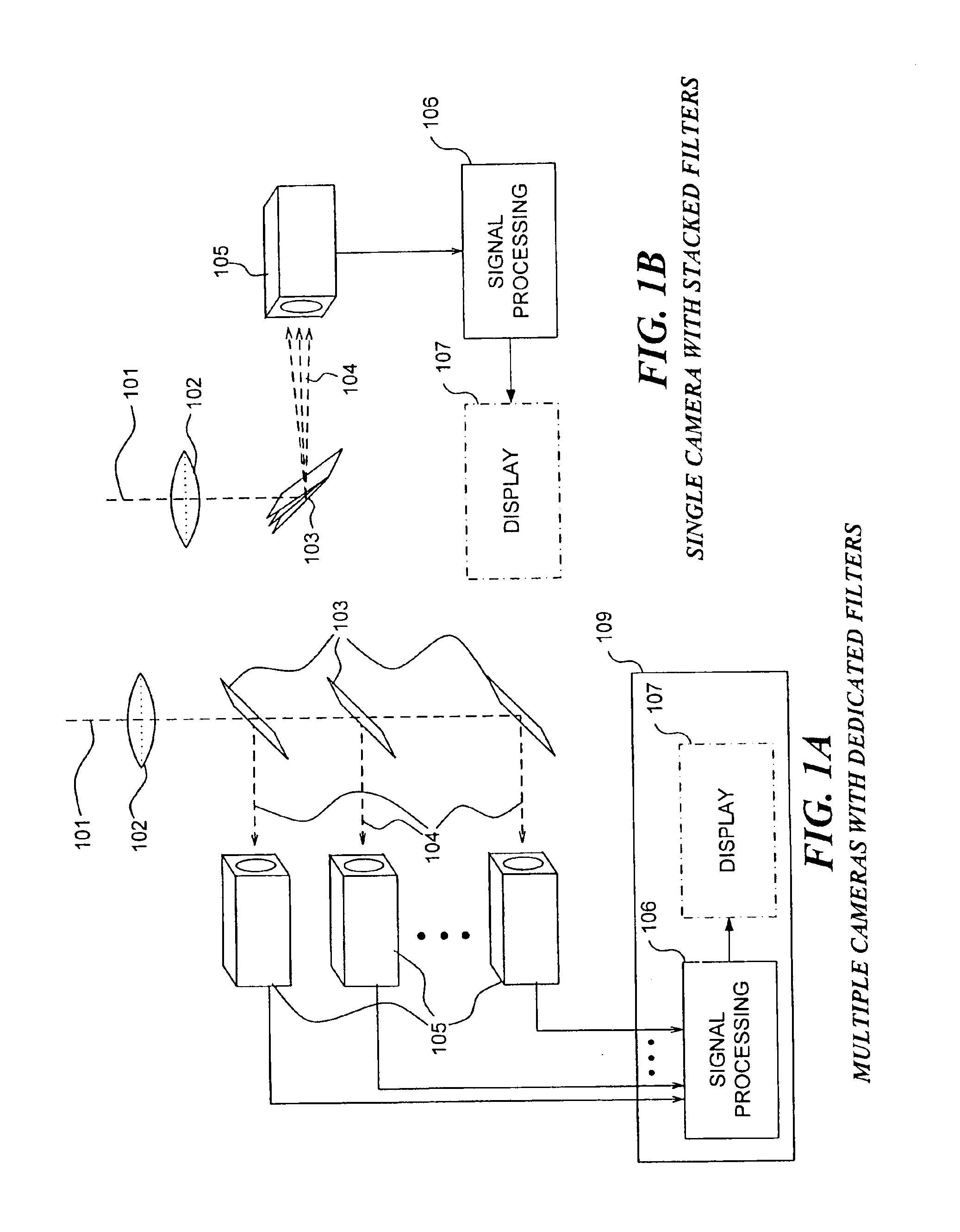
[0059]FIGS. 1A and 1B illustrate two configurations of an instrument for implementing the present invention. FIG. 1A shows an embodiment that utilizes a plurality of photosensitive cameras 105. Lens 102 is used to form images on the photosensitive detector arrays of cameras 105. The light along each image formation path 101 is filtered by specially designed mirrors 103 that transmit light in a first range of wavelengths and reflect light in a second range of wavelengths, defining a plurality of different wavebands that are received by individual cameras 105. The signals from cameras105 are processed by signal processing means 106, which aligns the signals relative to each other, and reduces crosstalk between signals. An optional element is a display 107, on which the plurality of images corresponding to the processed signals can be displayed to a user.

[0060]While display 107 will often be beneficially incorporated in such a system, such a display is not required. For example, a user...


PUM


Abstract

A multichannel imaging system generates an ensemble of images for each field of view of an object. Each image in the ensemble is intended to contain information from only one source among a plurality of sources for the object. However, due to crosstalk, at least a portion of the signal from a first source appears in a channel intended for a second source. Because the accuracy of the correction will be degraded if the images in an ensemble are spatially misaligned with respect to one another, the spatial offset between images is determined and a correction is applied to substantially eliminate the offset. Then, a correction to the signals is determined to substantially reduce the contributions to the signal in a channel from the signals in other channels. The signal processing can be employed to process the output signals for each of a plurality of different disclosed imaging systems.

Description

RELATED APPLICATIONS[0001]This application is a U.S. divisional patent application based on prior application Ser. No. 10 / 132,059 now U.S. Pat. No. 6,763,149, filed Apr. 24, 2002, which in turn is a U.S. conventional patent application based on prior provisional application Ser. No. 60 / 286,713, filed Apr. 25, 2001, the benefits of the filing dates of which are hereby claimed under 35 U.S.C. § 119(e) and 120.FIELD OF THE INVENTION[0002]The present invention generally relates to a method and apparatus for improving the accuracy of quantitative images generated by multichannel imaging instruments, and more specifically, to correcting errors introduced by crosstalk between channels, with application to a broad range of imaging instruments and particularly, to flow imaging instruments using time-delay-integration image detectors.BACKGROUND OF THE INVENTION[0003]The parallel advancement of the technology of video microscopy and techniques for preparing and staining biological samples has ...

Claims


Application Information

Patent Timeline
Patent Type & Authority Patents(United States)
IPC IPC(8): G06K9/32A61B6/00G01BG06K9/00G06K9/03G06K9/40G06K9/68G06T5/00G06T5/50G06T7/00
CPCG01J3/28G01J3/2803G01J3/32G01J3/36G06K9/00127G06K9/00503G06T5/50G06T7/0026G06T7/0028G01N15/147G06T2207/10036G01N15/1475G06T7/32G06T7/33G06V20/69G06F2218/02
Inventor RILEY, JAMES K.FROST, KEITH L.
Owner CYTEK BIOSCI
Why Eureka
Try Eureka