Method and system for extracting data from surface array deposited features

a technology of surface arrays and features, applied in the field of molecular array or biochip analysis, can solve the problems of large deviation, noise and variation in scanned images of molecular array features, and achieve the effect of facilitating this process and high signal-to-noise ratio

Inactive Publication Date: 2006-02-28
AGILENT TECH INC
View PDF3 Cites 34 Cited by
  • Summary
  • Abstract
  • Description
  • Claims
  • Application Information

AI Technical Summary

Benefits of technology

[0009]One embodiment of the present invention comprises a method and system for automated feature extraction from scanned images produced by optical, radiometric, or other types of analysis of molecular arrays. First, horizontal and vertical projections of pixel values, called row and column vectors, are computationally produced from the scanned image. The row and column vectors are analyzed to determine the positions of peaks, and the positions of the first and last peaks in the row and column vectors are used to estimate the positions of the corner features within the scanned image. Typically, bright control features, i.e. features designed to hybridize to labeled sample molecules of any sample solution to which a molecular array is exposed, are placed on the border of the molecular array to facilitate this process. When necessary, row and column vectors can be calculated over a range of rotations of a two-dimensional, orthogonal coordinate system in order to select the most favorable rotation angle at which to fix the coordinate system. Analysis of regions of the scanned image representing the corner features can be used to more exactly locate the positions of the corner features. Then, using the established positions of the corner features, an initial coordinate system is com

Problems solved by technology

However, background signals, such as the background signal represented by non-zero pixel 202, may arise from non-specific binding of labeled molecules due to imprecision in preparation of molecular arrays and/or imprecision in the hybridization and washing of molecular arrays, and may also arise from imprecis

Method used


Image

  • Method and system for extracting data from surface array deposited features
  • Method and system for extracting data from surface array deposited features
  • Method and system for extracting data from surface array deposited features

Examples


Embodiment Construction

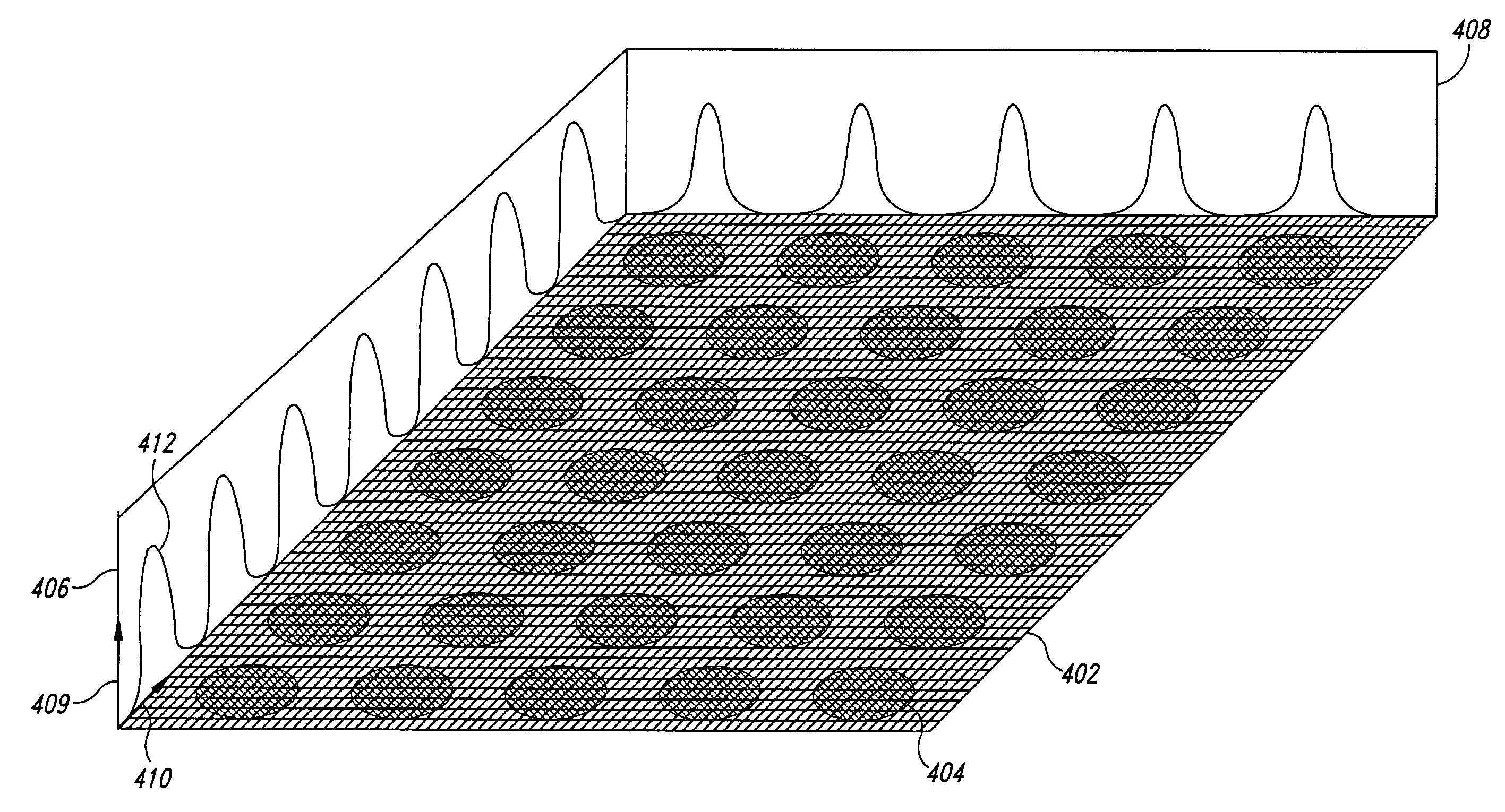
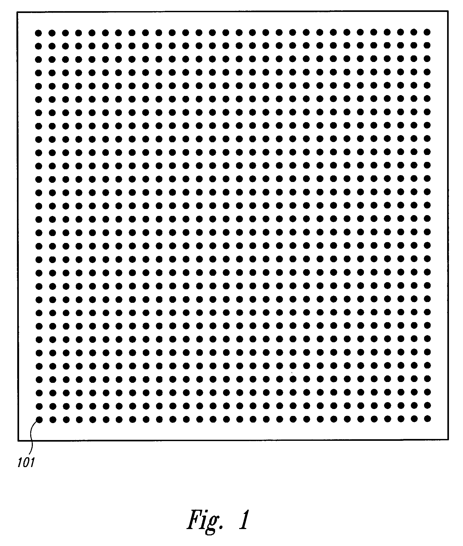
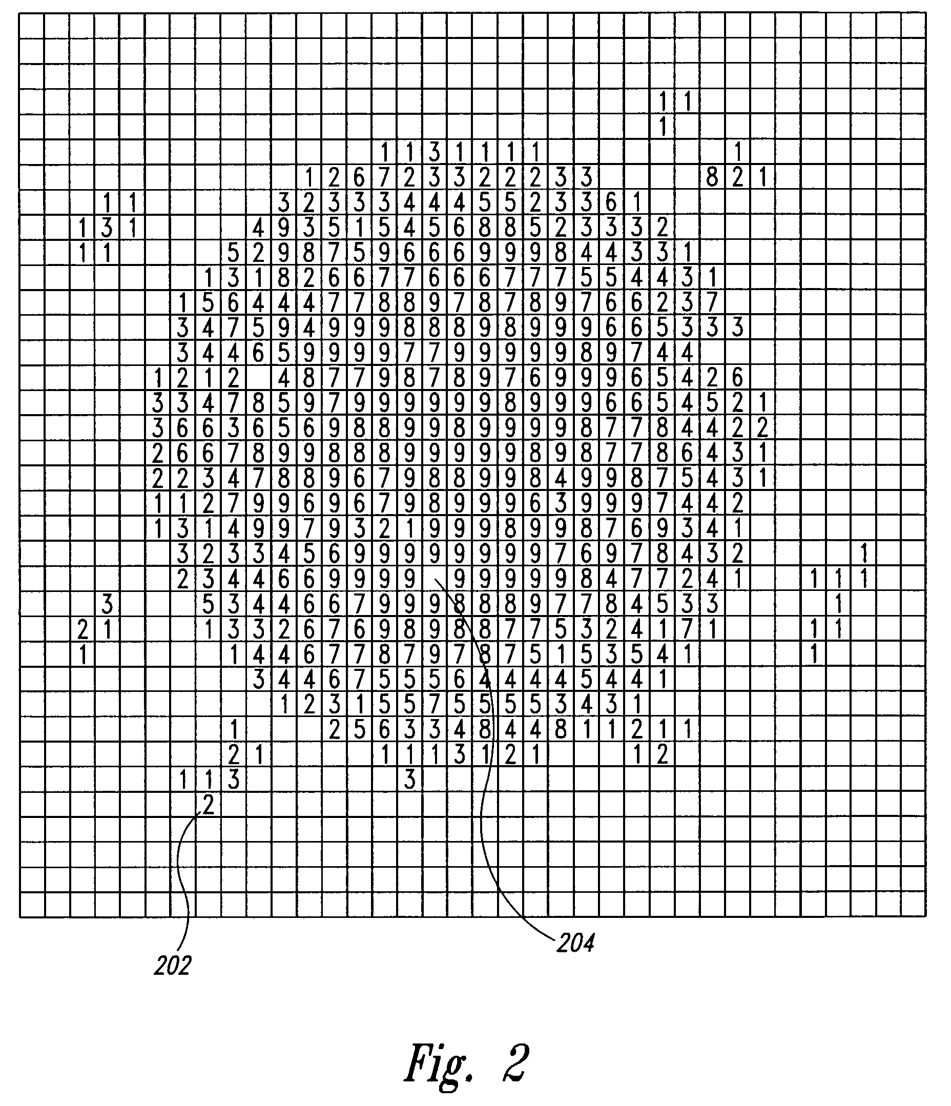
[0049]The present invention is directed toward automated feature extraction from scanned images of molecular arrays. Automated feature extraction includes: (1) a determination of the approximate positions of the features, for example by determining the positions of corner features within the scanned image; (2) generation of an initial coordinate system for the scanned image, for example, by using the positions of corner features, or by alternative means, including using mechanically precise positioning of features on the molecular array and of the molecular on the detection device and by using fiducial reference marks incorporated in the molecular array and detected independently, but in spatial alignment with detection of chemical features, and refinement of the initial coordinate system to produce a refined coordinate system; (3) determination of reliable regions of the scanned image from which to extract signal data; (4) and extraction of signal data from the features and local b...


PUM


Abstract

A method and system for extracting data signals from a scanned image resulting from optical, radiometric, or other types of analysis of a molecular array. The positions of corner features are first located. Then, an initial feature coordinate grid is determined from the positions of the corner features. A refined feature coordinate grid is then calculated based on the positions of strong features, and is used to identify the positions of weak features and the positions of the local background regions surrounding all features. Finally, signal intensity values are extracted from the features and their respective local background regions in the scanned image, and background-subtracted signal intensity values, background-subtracted and normalized signal intensity ratios, and variability information and confidence intervals are determined based on the extracted values.

Description

CROSS-REFERENCE TO RELATED APPLICATIONS[0001]This application is a continuation-in-part of U.S. patent application Ser. No. 09 / 589,046 “Method And System For Extracting Data From Surface Array Deposited Features”, filed Jun. 6, 2000 now U.S. Pat. No. 6,591,196 by Enderwick, et al., from which priority is claimed and which is incorporated herein by reference.TECHNICAL FIELD[0002]The present invention relates to the analysis of molecular arrays, or biochips, and, in particular, to a method and system for processing a scanned image of a molecular array in order to index the regions of the image that correspond to features of the molecular array and to extract data from indexed positions within the scanned image that correspond to optical or radiometric signals emanating from features of the molecular array.BACKGROUND OF THE INVENTION[0003]Molecular arrays are widely used and increasingly important tools for rapid hybridization analysis of sample solutions against hundreds or thousands ...

Claims


Application Information

Patent Timeline
IPC IPC(8): G06F11/32G06T7/00
CPCG06T7/0042G06T2207/30072G06T7/73
Inventor YAKHINI, ZOHARENDERWICK, CYNTHIA Y.DELENSTARR, GLENDA C.WOLBER, PAUL K.SAMPAS, NICHOLAS M.CATTELL, HERBERT F.CONNELL, SCOTT D.
Owner AGILENT TECH INC
Why Eureka
Try Eureka