Vertical boxless mould casting machine

a mould casting machine and vertical box technology, applied in the field of vertical boxless mo, can solve the problems of affecting reducing the quality of parts obtained, and affecting the bottom area of the shell to suffer wear

Inactive Publication Date: 2006-03-07
LORAMENDI
View PDF14 Cites 21 Cited by
  • Summary
  • Abstract
  • Description
  • Claims
  • Application Information

AI Technical Summary

Problems solved by technology

This advance method for the shells has two obvious drawbacks: on one hand, the wear suffered by the bottom area of the shells as they rub against the floor when traveling through the installation; and, on the other, the compression of the shells as they are pushed by the extraction piston to make the entire row advance.
With this type of installation the shells are subject to friction against the rails that form the conveyor system, so that in this case there would also be wear damaging the shell that may affect the quality of the parts obtained.
Furthermore, the lateral clamps must apply a great pressure on the last shell, as they must prevent the recession of the entire row of shells when the conveyor rails recede, thus resulting in compressions and deformations of this last shell that also reduce the quality of the parts obtained.
In addition, the following or pushing by the extraction piston in the initial movement of the shell until it is placed on the conveyor system requires a perfect synchronization of the motions of the conveyor system and the extraction piston, as otherwise slight differences in the position and / or speed may occur that would lead to friction between the shells, which would in turn result in a wear of the sand mold and eventually cause defects in the part.

Method used


Image

  • Vertical boxless mould casting machine
  • Vertical boxless mould casting machine
  • Vertical boxless mould casting machine

Examples


Embodiment Construction

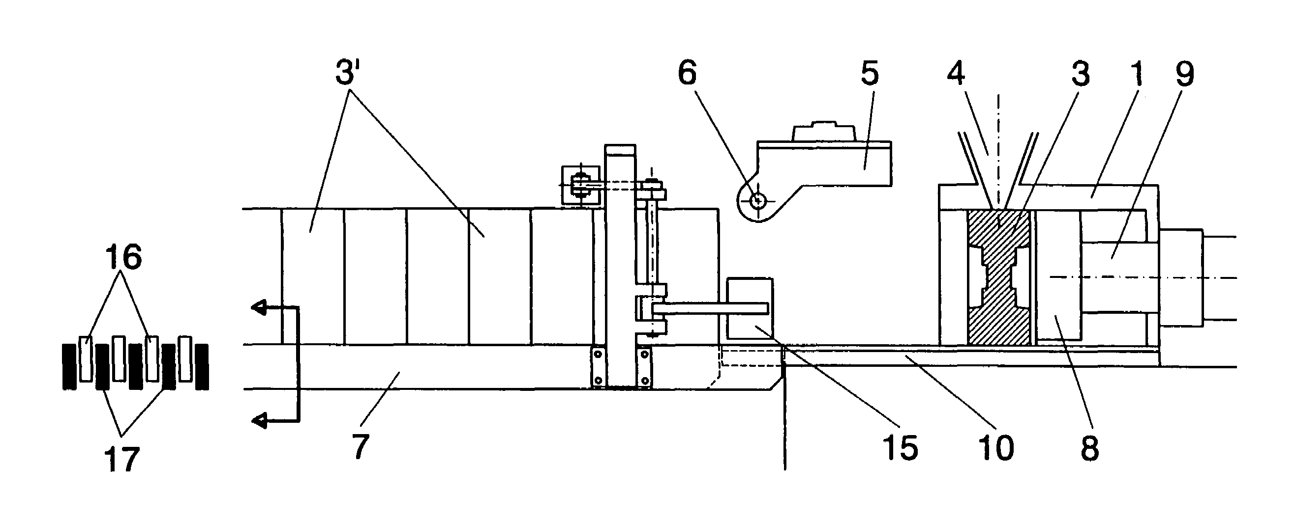
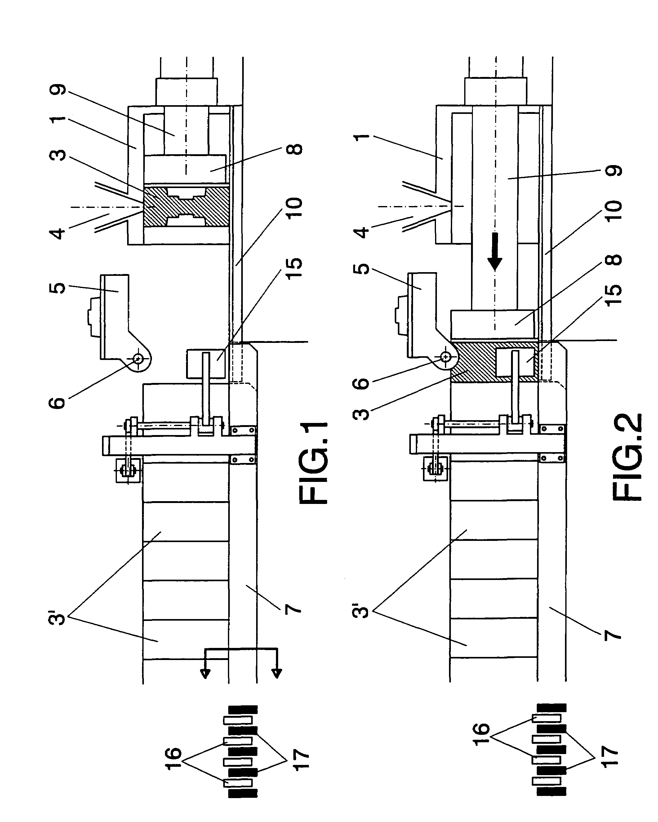
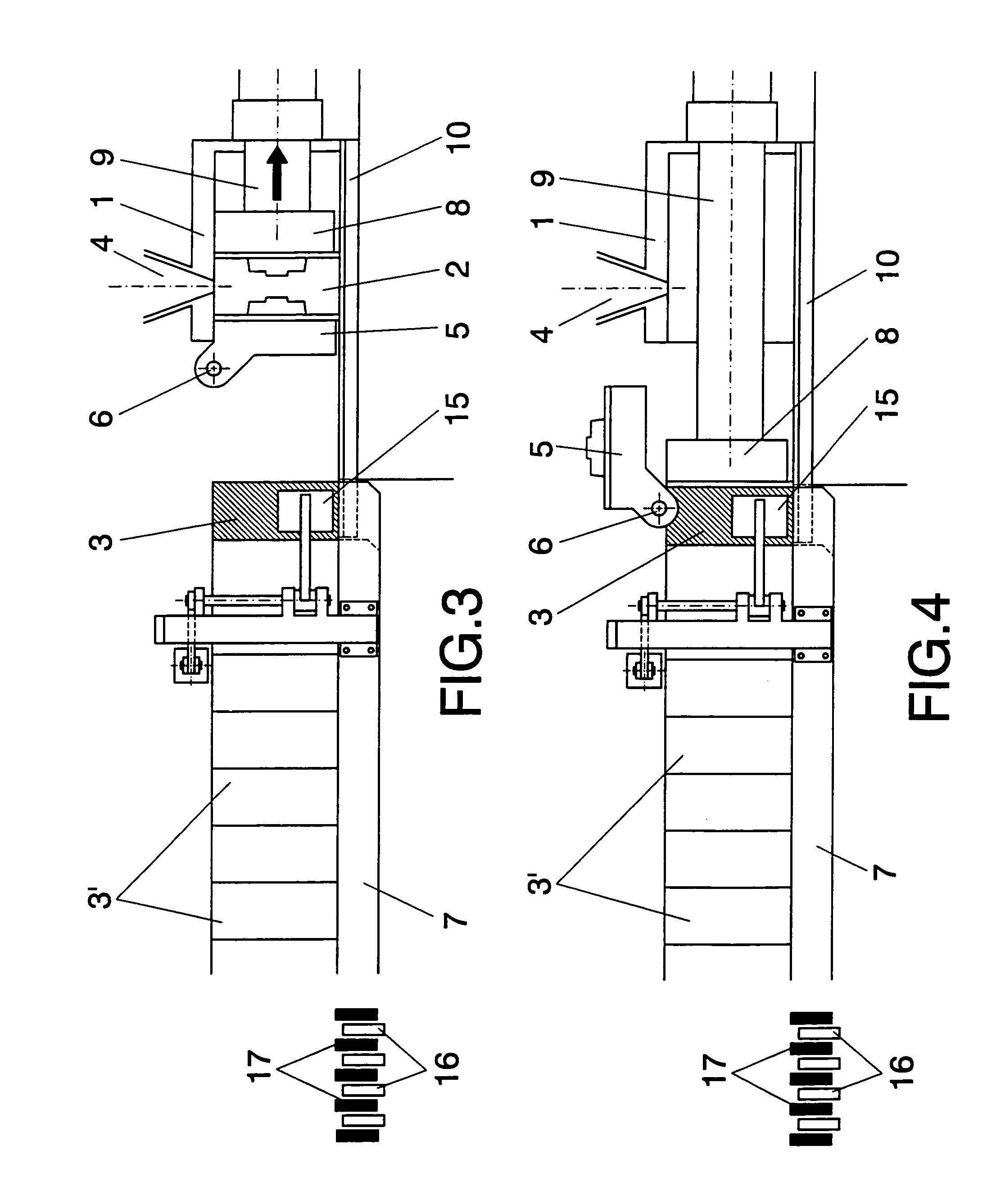
[0014]The vertical shell molding machine of the invention has been conceived to solve the aforementioned problems by making the motion of the shell, pushed by the extraction piston, completely independent of the movement of the row of shells; that is, the shell is pushed by the extraction piston according to the molding sequence and not according to the movement of the conveyor system. For this purpose, the extraction piston places the shell in an intermediate position defined on the end of the baseplate of the molding station, that is not part of the conveyor system, so that the extraction piston does not participate at any time in the advance of the row of shells as it travels along the installation. Thus, the row of shells does not advance by being pushed by the last shell extracted by the extraction piston but instead by the action of an independent conveyor system, so that as the motions of the extraction piston and the conveyor system are independent after the shell is obtaine...


PUM

PropertyMeasurementUnit
pressuresaaaaaaaaaa
pressureaaaaaaaaaa
melt pressureaaaaaaaaaa

Abstract

The molding machine comprises a station (1) with a chamber (2) that is closed between a front plate (5) that can move and swivel and a rear plate (8) associated to an extraction piston (9), forming a shell (3) in said chamber (2) by blowing sand through an upper hopper (4). The shell (3) obtained is pushed by the piston (9) until the rear of a row of shells (3′) placed on a conveyor (7) that places them opposite a casting station. The motion of the shell (3) pushed by the extraction piston (9) is independent of the motion of said piston after being incorporated in the row of shells, and is provided exclusively by the conveyor system (7), thereby providing a shorter working cycle while preventing deterioration of the shells as they are not compressed by the piston (9) when it pushes against the rear of the row of shells (3′).

Description

[0001]This application claims the benefit of International Patent Application No. PCT / ES01 / 00224 filed Jun. 1, 2001.OBJECT OF THE INVENTION[0002]The present invention relates to a vertical shell molding machine, improved in certain aspects to achieve an increased production by a shorter duration of the working cycle, as well as to prevent possible erosion, deformation or compressions of the shells, leading to an improved quality of the parts obtained.BACKGROUND OF THE INVENTION[0003]Shell molding machines basically consist of a molding chamber, fed by a sand hopper established above it, which chamber is closed by a movable swiveling front plate and by a rear plate established on the end of an extractor piston, with the sand being compacted by the opposing pressure of the two plates.[0004]In this way shells are cyclically obtained that form two half-molds and which are extracted with the aid of the extraction piston from the molding chamber and set against each other and aligned to f...

Claims


Application Information

Patent Timeline
Patent Type & Authority Patents(United States)
IPC IPC(8): B22C9/20B22C11/10B22D33/00
CPCB22D33/005B22C11/10
Inventor GOYA ARCELUS, IGNACIO
Owner LORAMENDI
Why Eureka
Try Eureka