Cover for a drainage arrangement and a method of producing such an arrangement

a drainage arrangement and cover technology, applied in the direction of paving details, ways, climate change adaptation, etc., can solve the problems of affecting the aesthetic effect, needing frames, and disrupting the appearance of the area to be drained, so as to achieve the effect of effectively conducting both surface runoff and percolating water, and being simple and economical to manufactur

Inactive Publication Date: 2006-03-07
ACO SEVERIN AHLMANN GMBH & CO KG
View PDF10 Cites 9 Cited by
  • Summary
  • Abstract
  • Description
  • Claims
  • Application Information

AI Technical Summary

Benefits of technology

[0006]The object of the invention is to provide an inconspicuous drainage system both for a superficial level and also for a deeper level, which is simple and economical to manufacture, that can be installed in the ground, and that can effectively conduct away both surface runoff and percolating water.

Problems solved by technology

The presence of grating-type drain covers impairs the aesthetic effect of the pattern of paving stones, and the appearance of the area to be drained is disrupted by the contours of the drainage system.
Disadvantages of such drainage systems are on one hand the need for frames, which much be matched to the size of the particular paving stones or hollow blocks being used, and on the other hand the difficulty of fitting the frames to the channels when the area is being paved.
When a separating or sealing layer is provided below the pavement, to ensure that water percolating through the pavement is prevented from entering underground structures such as a parking garage, this percolating water must be conducted away through many separate, punctate drainage holes, which is complicated and expensive.

Method used


Image

  • Cover for a drainage arrangement and a method of producing such an arrangement
  • Cover for a drainage arrangement and a method of producing such an arrangement
  • Cover for a drainage arrangement and a method of producing such an arrangement

Examples


Embodiment Construction

[0021]In the following description, the same reference numerals are used for identical parts or parts with identical actions.

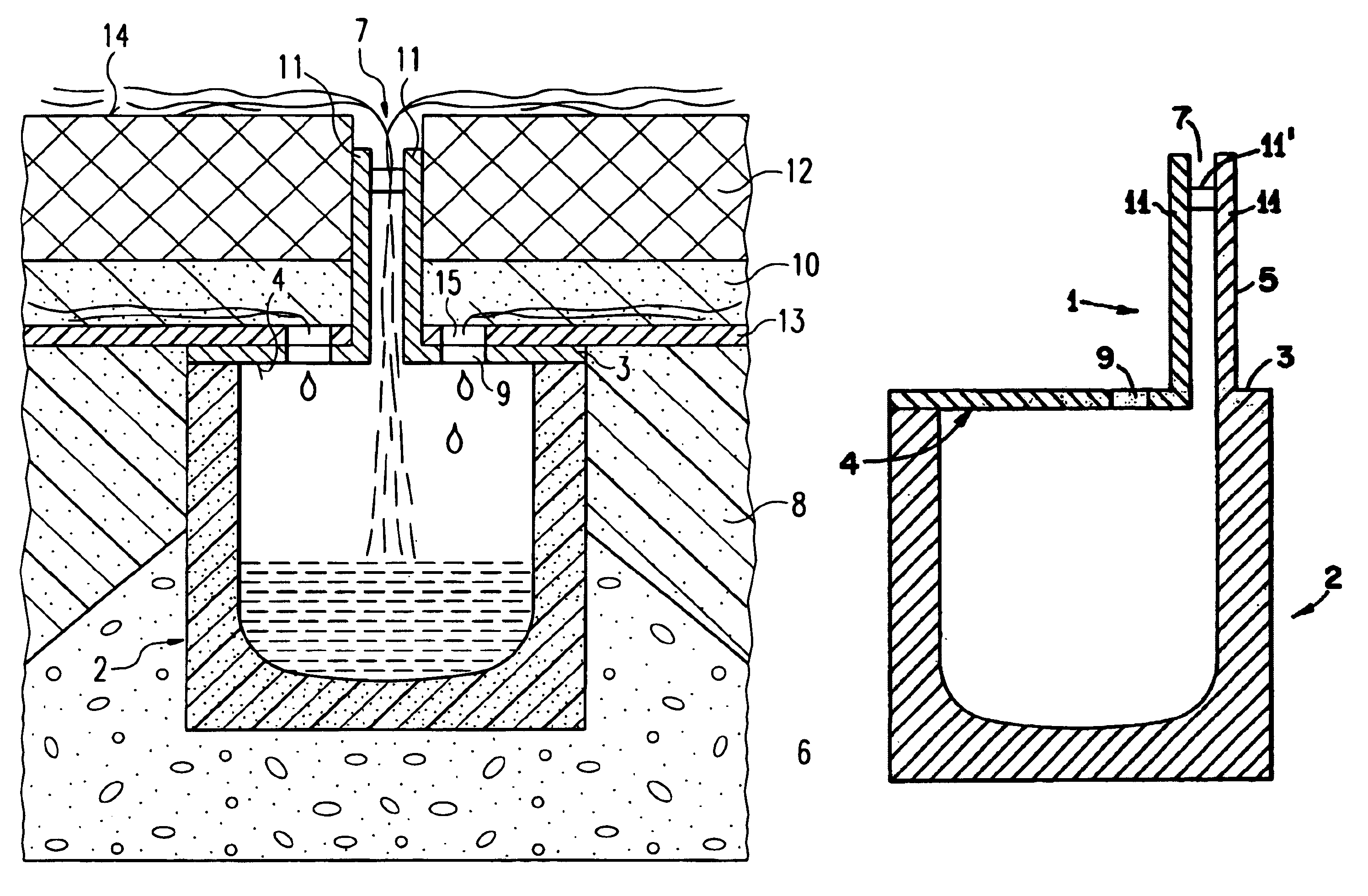
[0022]In the case of large surface areas, linear drainage systems are used. These comprise a network of drains running under the surface of the ground. The drains are constructed of individual channels made of concrete polymer and connected to one another, on the apertures at the top of which covers are mounted.

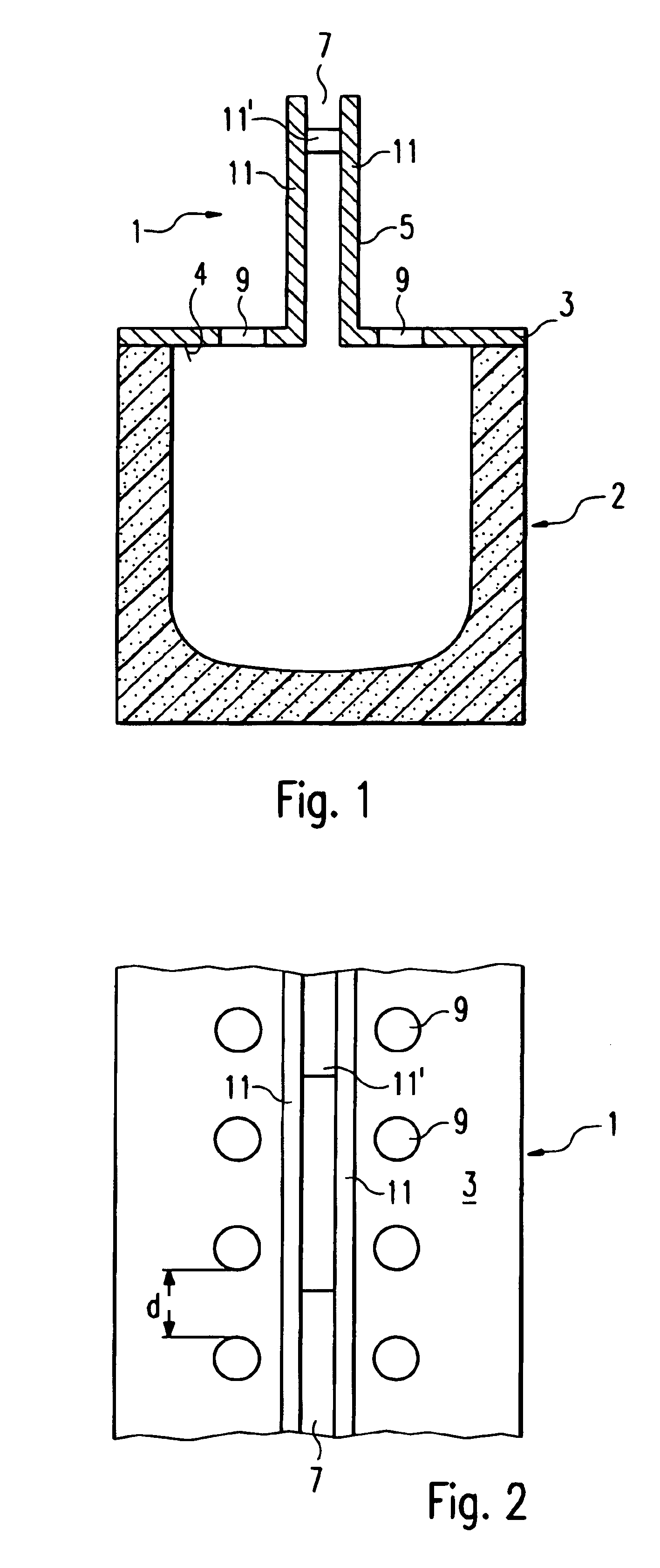
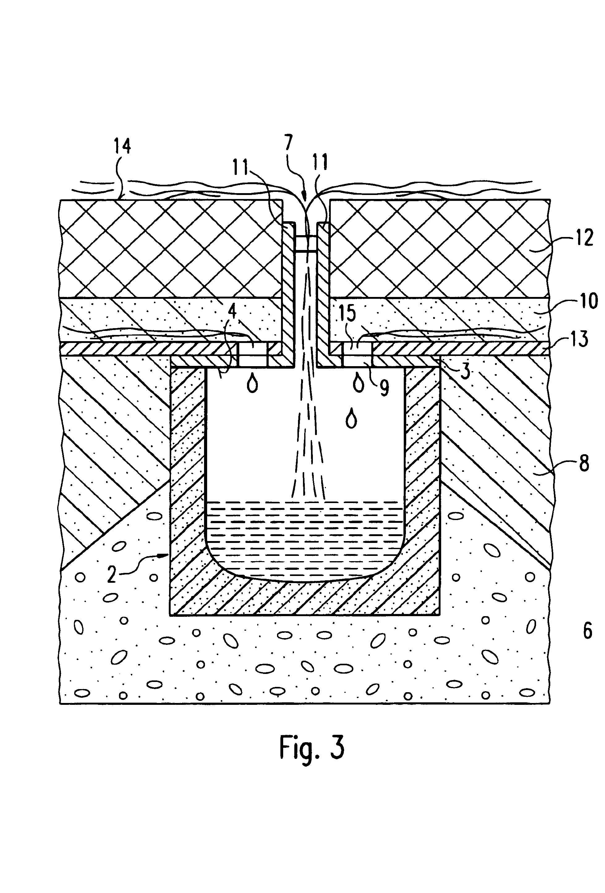
[0023]FIG. 1 shows in cross section a U-shaped drainage channel 2 on which is mounted a cover 1 in accordance with the invention, made of stainless steel. The cover 1 in accordance with the invention is fixed to the drainage channel 2 by a form-fitting or similar connection. Alternatively, the cover 1 can be seated freely on a steel frame integrated with the channel. The cover 1 is so formed as to cover an opening 4 at the top of the drainage channel 2 and consists of a planar portion 3 and a vertical projection 5 that extends upward from the planar por...


PUM


Abstract

The invention relates to a cover (1) for a drainage channel (2) to be installed in the ground to drain the surface of an area. The cover (1) comprises a substantially planar portion (3) which is constructed so as to cover an opening at the top of the drainage channel (2) and which comprises a projection (5) that extends upward from the planar portion (3). The projection (5) defines an inlet (7) through which the water that runs off from the surface to be drained can enter the drainage channel. In addition, the planar portion (3) defines comprises supplementary apertures (9) to receive water that has percolated down to its lower level.

Description

FIELD OF THE INVENTION[0001]The present invention relates to a cover for a drainage channel to be installed in the ground to drain the surface of an area, and to a method of producing a drainage arrangement incorporating the cover.BACKGROUND OF THE INVENTION[0002]Drainage systems for conducting away surface water collected from a large area, such as a pedestrian zone and comparable areas for parking cars, underground garages and so on are already known. For such large areas linear drainage systems are used, in which a set of individual channels lined up in a row are buried in the ground and the openings at the tops of the channels are covered with gratings shaped in various ways and made of diverse materials. However, it is becoming increasingly common to pave areas of this kind not with concrete or asphalt but rather with paving stones or hollow blocks. The presence of grating-type drain covers impairs the aesthetic effect of the pattern of paving stones, and the appearance of the ...

Claims


Application Information

Patent Timeline
Patent Type & Authority Patents(United States)
IPC IPC(8): E01F5/00E01C11/22
CPCE01C11/225E01C11/228E01C11/227Y02A30/30
Inventor MULLER, MICHAEL
Owner ACO SEVERIN AHLMANN GMBH & CO KG
Why Eureka
Try Eureka