Modified Savonius rotor

a rotor and wind turbine technology, applied in the direction of wind motors with perpendicular air flow, liquid fuel engine components, non-positive displacement fluid engines, etc., can solve the problems of low efficiency of savonius rotor, no prior art discloses exhaust ports, and no prior art discloses the use of savonius rotor vanes as a surfa

Inactive Publication Date: 2006-03-07
CIRCLE WIND CORP
View PDF9 Cites 109 Cited by
  • Summary
  • Abstract
  • Description
  • Claims
  • Application Information

AI Technical Summary

Benefits of technology

[0017]An object of the present invention is to provide a flow path for exiting air from a Savonius rotor without passing through a channel produced by a first and second vanes.
[0018]To effect the modification of a Savonius rotor, the two vanes are formed in a single “S” shapes vane and channels are provided, preferably along a lower edge of the vane and extending at least halfway up the vane. Through the channel is a flow path for the air to pass through the vane from the convex portion of the vane to the freestream. In shape, the exhaust channel transitions smoothly fro...

Problems solved by technology

Drawbacks of such an arrangement are the need to have the power unit (generator, air compressor, etc.) on top of the tower with the airfoils, or the need for gearing to transfer the power toward the ground.
However, in its traditional form (see FIG. 1), the Savonius rotor is kno...

Method used


Image

  • Modified Savonius rotor
  • Modified Savonius rotor
  • Modified Savonius rotor

Examples


first embodiment

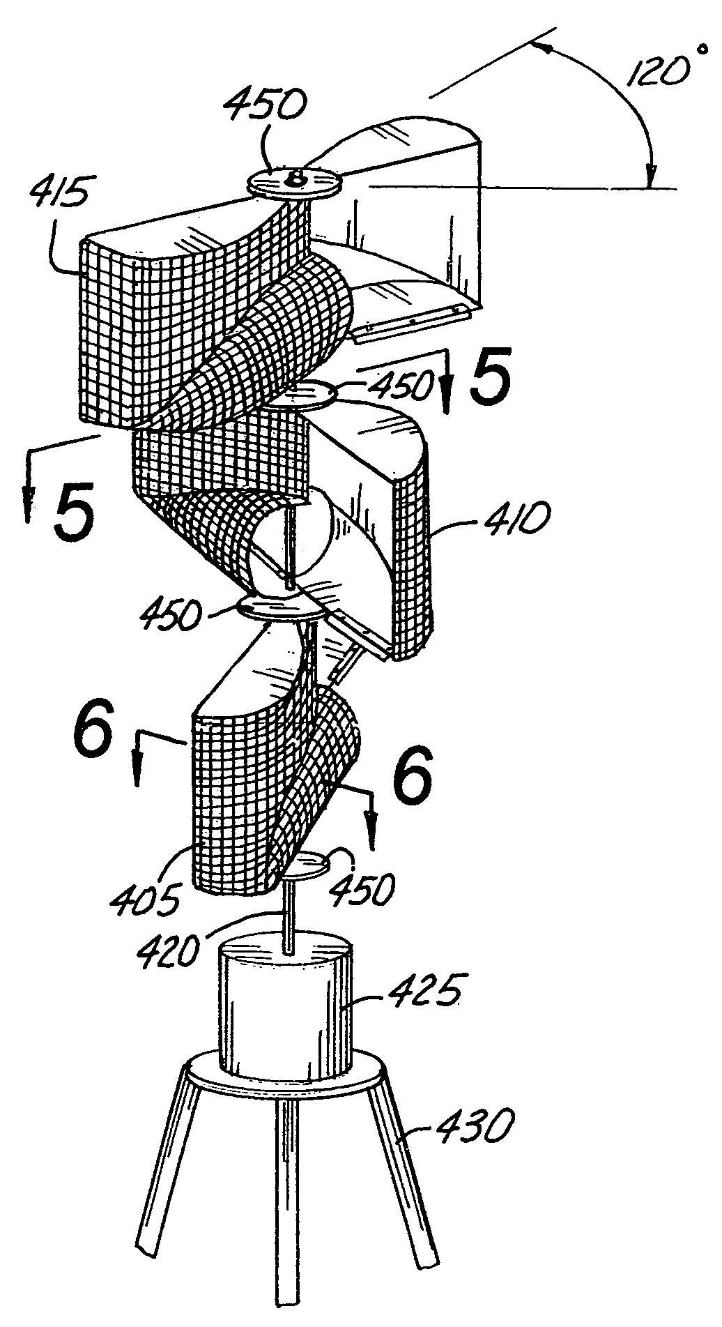
[0049]A set of three (3) modified Savonius rotors 405, 410, 415 are shown stacked vertically in FIG. 4 in a rotor assembly 400 in the invention. By angling the “S” shaped vanes differently for each set (in this case 120° apart), automatic startup is assured because at least one rotor will be turned such that the change in momentum of the wind will cause the assembly to turn. The set of modified Savonius rotors 405, 410, 415 in the assembly 400 are rigidly affixed to a shaft 420 which rotates as the modified Savonius rotors 405, 410, 415 rotate. A bearing (not shown) at a lower end of the shaft 420 provides reduced friction rotation. Via the shaft 420, power is transmitted to a power converting device 425 such as an electrical generator, an air compressor, pump, etc. An advantage of the Savonius rotor over horizontal-shaft wind turbines is the ability to locate the power converting device 425 at or near ground level where it is accessible for installation, maintenance, repair, and in...

second embodiment

[0064]the present invention is shown in FIG. 18 wherein larger support plates 1810 are used in place of the smaller support plates 450 shown in FIGS. 4 and 5 and no photovoltaic cells are utilized. In this preferred embodiment, each support plate 1810 is attached to the top flange 510 and bottom flange 610 by bolts or rivets as shown. Other possibilities for adjoining a support plate 1810 and a vane 710 are by adhesive or combining the top and bottom flanges 510, 610 into one support plate 1810.

[0065]The view shown in FIG. 19 is similar to that of FIG. 6 with the addition of the larger support plate 1810 and the absence of solar collecting material. Again, a metallic edge 1910 is provided on the leading edge of the bottom flange 610. A detail of a cross section of the vane 710 and metallic edge 1910 is shown in FIG. 20. The metallic edge 1910 has a sharpened leading edge to reduce the disturbance to the boundary layer of the flow over the support plate 1910 and bottom flange 610.

[00...

third embodiment

[0071]the modified Savonius rotor assembly 400 is shown in FIG. 28 wherein the assembly shown in FIG. 18 is outfitted with the addition of a cone-shaped solar collector 2810 at its top. Separate isosceles triangular sections 2820 of photovoltaic solar cells are creased so as to have a ridge running from the top apex to the base. These individual triangular sections 2820 are adjoined to produce the cone shape. As shown, the cone has an included angle of 120°.


PUM


Abstract

A novel modification of a Savonius rotor used as a wind turbine provides an exhaust channel in each vane. The vane of the modified Savonius rotor is formed into an “S” shape. The air that enters a given end of the vane exits that end through the new exhaust channel into the freestream. A plurality of modified Savonius rotors are stacked one on top of the other for self-starting and greater power output. The outer surfaces of the entire assembly may be coated with photo voltaic cell material for additional energy production. In one embodiment of the invention, a cone shaped solar collector is placed on top of the entire modified Savonius rotor assembly.

Description

CROSS REFERENCE TO RELATED APPLICATIONS[0001]Not applicable.STATEMENT REGARDING FEDERALLY SPONSORED RESEARCH OR DEVELOPMENT[0002]Not applicable.REFERENCE TO MICROFICHE APPENDIX[0003]Not applicable.BACKGROUND OF THE INVENTION[0004]1. Field of the Invention[0005]The present invention relates generally to an alternate source of energy. More particularly the present invention relates to a modification to a Savonius wind turbine rotor for converting kinetic energy in the wind to shaft power.[0006]2. Background Art[0007]Shaft power has been derived from the wind for centuries. Dutch windmills were first used for grist, and later converted to raising water to sea level for land reclamation. Wind power was commonly harnessed across the prairie and plains states in the U.S. for pumping water from wells. In the early part of the 20th century, wind was utilized for converting kinetic energy to electrical energy.[0008]The last quarter of the 20th century saw a marked increase in interest in con...

Claims


Application Information

Patent Timeline
IPC IPC(8): F03D7/06
CPCF03D3/061F03D9/007Y10S415/907Y02E10/74F05B2240/213F03D9/25H02S10/12Y02E10/50
Inventor WHITWORTH, ART
Owner CIRCLE WIND CORP
Why Eureka
Try Eureka