
Multi-compliance voltage generator in a multichannel current stimulator

a multi-component, current stimulator technology, applied in the direction of power conversion systems, electrical equipment, apparatus without intermediate ac conversion, etc., can solve the problems of reducing battery life, requiring surgery to replace batteries or the entire device, etc., to achieve the effect of reducing time and energy, and low effor

Inactive Publication Date: 2006-03-07
BOSTON SCI NEUROMODULATION CORP
View PDF16 Cites 45 Cited by
  • Summary
  • Abstract
  • Description
  • Claims
  • Application Information

AI Technical Summary

Benefits of technology

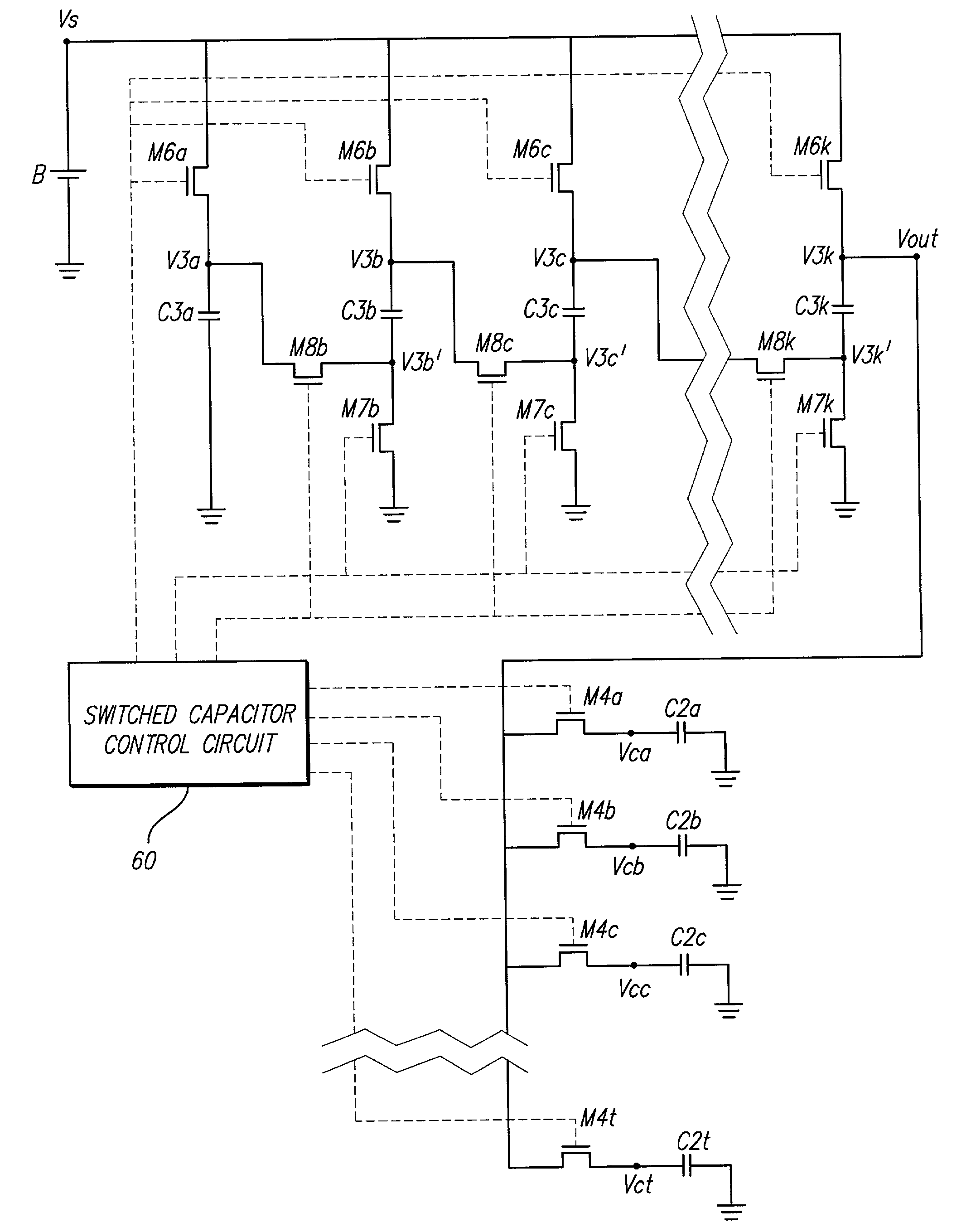
The present invention provides a multi-compliance voltage generator for implantable medical devices, particularly a multi-channel stimulation system like Spinal Cord Stimulation (SCS). The generator comprises a power source, an inductor, a first switch, a diode, a multiplicity of small capacitors, and a multiplicity of switches. The small capacitors are controlled to charge to the required compliance voltage of each stimulation channel. The generator provides separate compliance voltage for each channel, minimizing power dissipation and ensuring efficient use of power. The use of multiple small capacitors instead of a single large capacitor reduces the time and energy required to charge the capacitors. The invention also includes an improved switched capacitor power supply that replaces the single large capacitor with a multiplicity of small capacitors and switches to efficiently provide a multiplicity of voltages for use within a system.

Problems solved by technology

Inefficient use of power results in more frequent recharging of the battery, and thereby reduces battery life.
When the battery no longer is capable of holding a sufficient charge, surgery is required to replace the battery or the entire device.

Method used


Image

  • Multi-compliance voltage generator in a multichannel current stimulator
  • Multi-compliance voltage generator in a multichannel current stimulator
  • Multi-compliance voltage generator in a multichannel current stimulator

Examples


Embodiment Construction

[0023]The following description is of the best mode presently contemplated for carrying out the invention. This description is not to be taken in a limiting sense, but is made merely for the purpose of describing the general principles of the invention. The scope of the invention should be determined with reference to the claims.

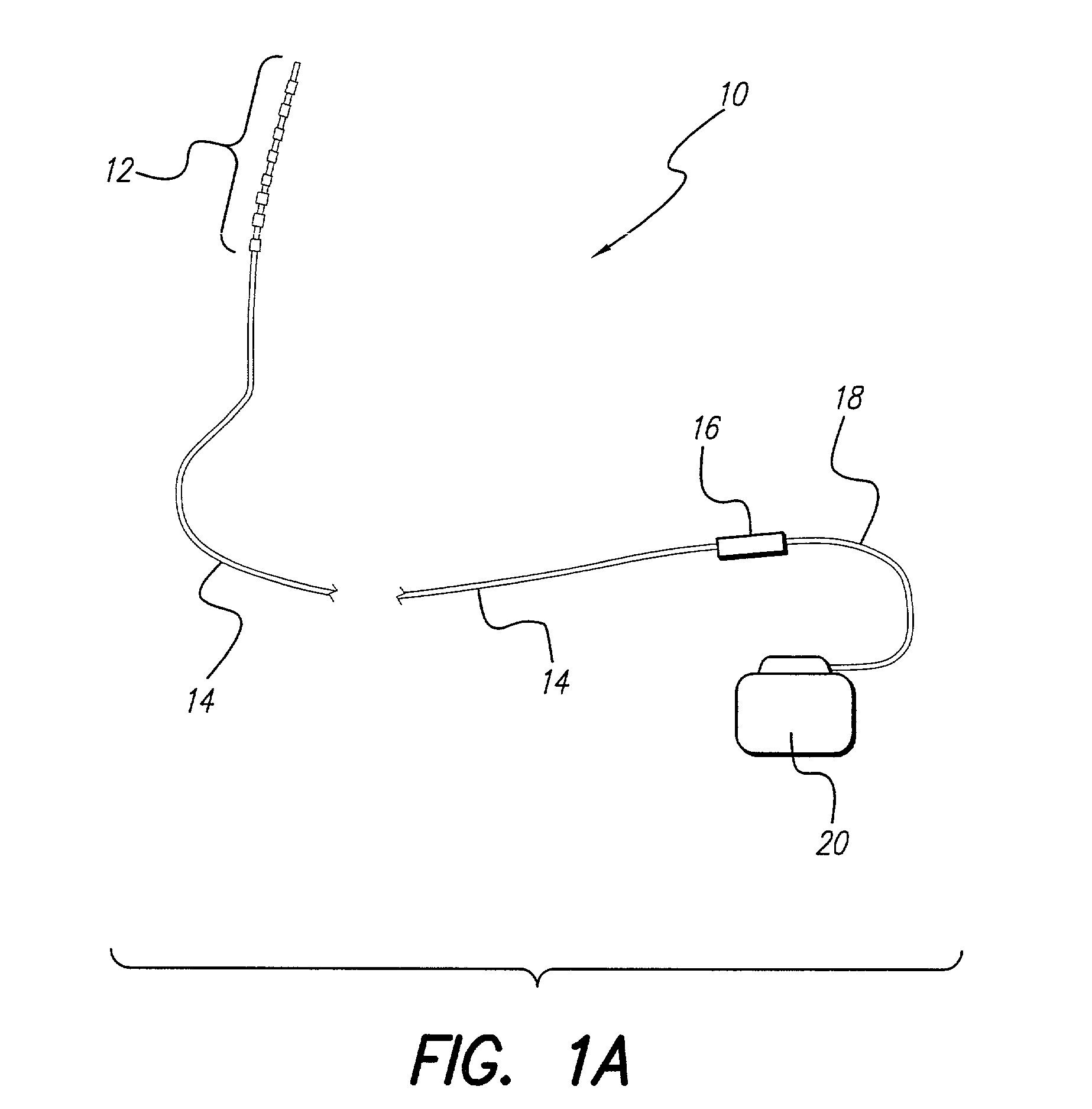
[0024]Implantable medical devices are used for many purposes. The present invention is directed to an implantable electrical stimulator. A preferred electrical stimulator is a Spinal Cord Stimulation (SCS) system 10 shown in FIG. 1A. Typically, an SCS system 10 is used to treat certain classes of intractable pain. The SCS system 10 comprises an electrode array 12, an electrode lead 14, a lead extension connector 16, a lead extension 18, and an Implantable Pulse Generator (IPG) 20.

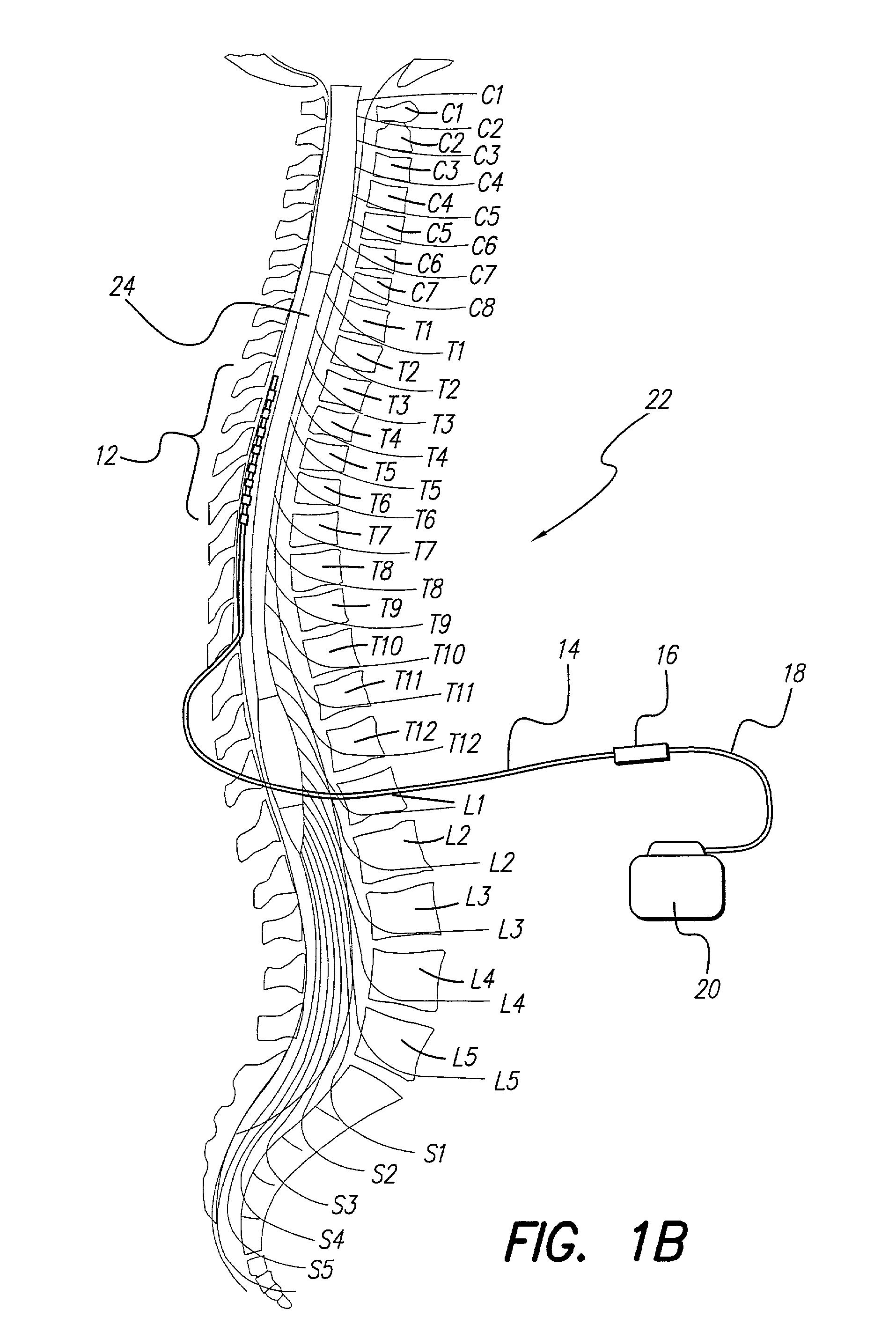
[0025]A typical SCS system 10 implanted in a spinal column 22 is shown in FIG. 1B. The electrode array 12 is implanted next to the spinal cord 24 and provides pain-blocking electric...


PUM


Abstract

An improved multi-voltage power supply charges individual small capacitors to different voltages. Each small capacitor is assigned to a circuit, and is charged to a voltage level sufficient for the circuit. In one embodiment, an improved switching regulator includes a multiplicity of small capacitors. The small capacitors are assigned to stimulation channels of a stimulation system. Each channel has a unique compliance voltage which the assigned small capacitors are charged to. By charging the small capacitors to the corresponding compliance voltages, versus charging a single large capacitor to the maximum compliance voltage, unnecessary power dissipation is avoided. In another embodiment, a switched capacitor power supply benefits from the present invention in the same manner as the switching regulator power supply. Further, any system requiring a plurality of different voltages may benefit from the present invention.

Description

[0001]The present application claims the benefit of U.S. Provisional Application Ser. No. 60 / 276,823, filed Mar. 16, 2001, which application is incorporated herein by reference.BACKGROUND OF THE INVENTION[0002]The present invention relates to implantable tissue stimulation systems, and more particularly to the independent generation of compliance voltages provided to each stimulation channel in an implantable multichannel tissue stimulation system such as a Spinal Cord Stimulation (SCS) system. A spinal cord stimulation system treats chronic pain by providing electrical stimulation pulses through the electrodes of an electrode array placed epidurally near a patient's spine. The electrode array is partitioned into channels including a current control circuit and cooperating electrodes. The level of stimulation in each channel is controlled by the current control circuit, and any excess power provided to a simulation channel is dissipated. Therefore, the independent generation of the ...

Claims


Application Information

Patent Timeline
Patent Type & Authority Patents(United States)
IPC IPC(8): H02J1/00
CPCH02M3/07H02M2001/009H02M1/009
Inventor PARRAMON, JORDIHE, YUPING
Owner BOSTON SCI NEUROMODULATION CORP
Learn More