Method and apparatus for launching a surfacewave onto a single conductor transmission line using a slohed flared cone

a technology of surface wave and transmission line, which is applied in the direction of waveguides, electrical devices, multiple-port networks, etc., can solve the problems of mechanical and electrical challenges, interference mismatch, and limitations of the designer and installer of such a devi

Active Publication Date: 2006-03-07
CORRIDOR SYST INC
View PDF2 Cites 700 Cited by
  • Summary
  • Abstract
  • Description
  • Claims
  • Application Information

AI Technical Summary

Benefits of technology

[0008]The present invention provides a method and apparatus for launching a surfacewave onto a single conductor transmission line. The inventive apparatus provides launch of a surfacewave onto either insulated or uninsulated single conductors making application to a variety of existing lines

Problems solved by technology

In addition to having excess transmission attenuation due to losses in the dielectric insulation, these designs suffer from significant impedance mismatch, unwanted conversion to radiating modes and resultant transmission attenuation of the surfacewave mode when a broad range of frequencies is supported, and require bo

Method used


Image

  • Method and apparatus for launching a surfacewave onto a single conductor transmission line using a slohed flared cone
  • Method and apparatus for launching a surfacewave onto a single conductor transmission line using a slohed flared cone
  • Method and apparatus for launching a surfacewave onto a single conductor transmission line using a slohed flared cone

Examples


first embodiment

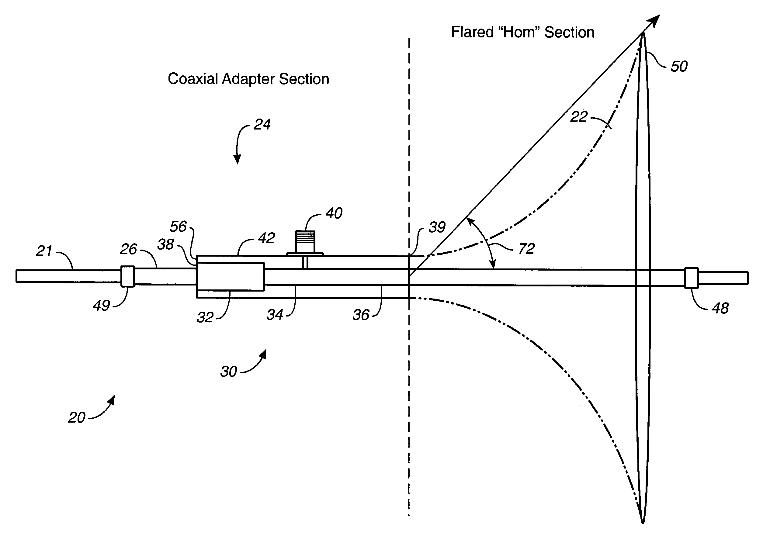
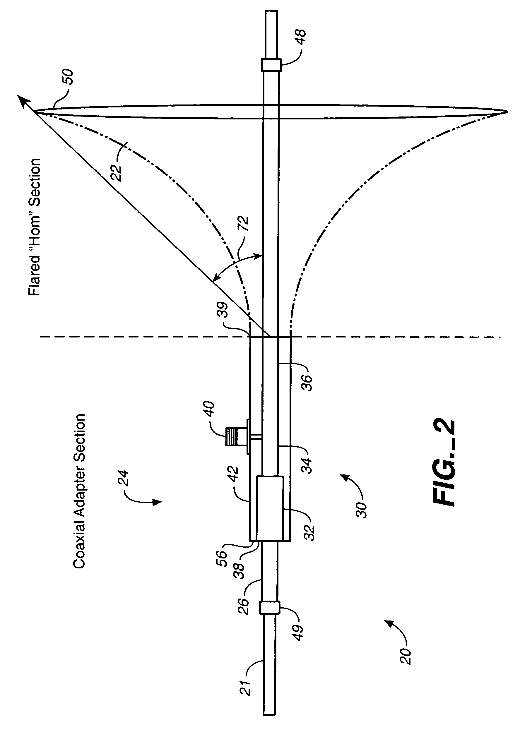
[0032]FIG. 2 is a side elevation cross-sectional view of the improved apparatus 20 for launching a surfacewave onto a single conductor transmission line 21 (either with or without an outer dielectric covering). Surfacewave launch 20 includes a flared horn or cone section 22, a coaxial adapter section 24, and a wire adapter portion 26.

[0033]The entire launch device may be cast or formed from a single piece of metal if desired. However, for the purpose of this description, construction of the inventive apparatus will be divided into sections for clarity as follows: (a) the construction of the coaxial adapter; (b) the construction of the flared cone or “horn”; and (c) the construction of the wire adapter. Construction here is described for use with coaxial connections with 50 ohm characteristic impedance, but other designs are possible by modifying the dimensions. Similarly, this description shows a launch apparatus designed to operate simultaneously on two US ISM bands centered around...

second embodiment

[0052]For the launch, as shown in FIGS. 5, 6A, 6B, 6C, dimensions and materials may be as follows:

[0053]

Flared Horn Length3.5 inchFlared Horn Mouth Diameter  7 inchCoupling1″ US Schedule L coppercouplingBushing1″ to ½″ US Schedule Lcopper bushingTriax Intermediate Conductor½″ US Schedule L copperpipeEnd, Shorting BlockAluminumCentral Wire Diameter.25 to .32 inchCoaxial Connectortype SMA or NDimension A (length of tapered portion of1.78 inchintermediate conductor)Dimension B (length by which central1.40 inchcoaxial cavity is greater than outer coaxialcavity)Dimension C (length of constant impedance .85 inchportion of central coaxial cavity that iscommon with outer coaxial cavity)Dimension D (length of central coaxial .75 inchcavity clamped by shorting block)

[0054]The completed surfacewave launch may be mounted to an existing single wire conductor as follows. For the first embodiment, illustrated in FIGS. 2, 3A, 3B, 4A, 4B, the wire adapter attachment devices (metal contacting tacks 5...


PUM


Abstract

An apparatus for launching a surfacewave onto a single conductor transmission line provides a launch including a flared, continuously curving cone portion; a coaxial adapter portion; a wire adapter portion for contacting the wire conductor which allows for a multiplicity of wire dimensions for either insulated or uninsulated wire, or a tri-axial wire adapter device enabling non-contacting coupling to a wire; and a longitudinal slot added to the flared cone, wire adapter, and coaxial adapter portions of the launch to allow direct placement of the launch onto existing lines, without requiring cutting or threading of those lines for installation.

Description

CROSS REFERENCE TO RELATED APPLICATIONS[0001]The present application claims the benefit of the filing date of U.S. Provisional Patent Application, Ser. No. 60 / 432,099, filed 09 Dec. 2002.STATEMENT REGARDING FEDERALLY SPONSORED RESEARCH OR DEVELOPMENT[0002]Not applicable.REFERENCE TO A MICROFICHE APPENDIX[0003]Not applicable.TECHNICAL FIELD[0004]The present invention relates generally to methods and apparatus for surfacewave transmission, and more particularly to an improved method and apparatus for launching a surfacewave onto a single wire transmission line.[0005]The present invention improves the performance and utility of previous launch devices for converting coaxial mode transmission to and from surfacewave mode transmission on a single conductor transmission line. This technology is related to transmission lines made from single conductor line having a thick outer dielectric sheath, an insulated wire, and known as a “Gobau line”, “G-line”, SWTL (surface wave transmission line)...

Claims


Application Information

Patent Timeline
IPC IPC(8): H01P3/10H01P5/02
CPCH01P3/10H01P5/08H01P5/02
Inventor ELMORE, GLENN E.
Owner CORRIDOR SYST INC
Why Eureka
Try Eureka