Adaptive variable true time delay beam-forming system and method

a true time delay and beam forming technology, applied in the field of detection of objects and/or areas, can solve the problems of difficult testing and calibration of the entire antenna system, and achieve the effect of reducing the complexity of the calibration process, reducing the amount of time required for system integration, and simplifying calibration and performance verification

Active Publication Date: 2006-03-07
LOCKHEED MARTIN CORP
View PDF12 Cites 25 Cited by
  • Summary
  • Abstract
  • Description
  • Claims
  • Application Information

AI Technical Summary

Benefits of technology

[0018]Many benefits may be achieved by way of the present invention over conventional techniques. For example, certain embodiments of the present invention reduce complexity of calibration process that usually involves physical manipulation of a large phased array antenna. Some embodiments of the present invention reduce the amount of time required for system integration in the factory. After system deployment, periodic maintenance procedures for periodic test, calibration and performance verifications can be simplified. Certain embodiments of the present invention can make real time measurements and estimate relative time delays and phase delays between received signals. Some embodiments of the present invention can lower the costs of making and using phased array antenna systems.

Problems solved by technology

As the size of the antenna aperture and the number of antenna elements become large, testing and calibration of the entire antenna system also become difficult.

Method used


Image

  • Adaptive variable true time delay beam-forming system and method
  • Adaptive variable true time delay beam-forming system and method
  • Adaptive variable true time delay beam-forming system and method

Examples


Embodiment Construction

[0040]The present invention relates in general to detecting objects and / or areas. More particularly, the invention provides a method and system for adaptive variable true time delay beam forming. Merely by way of example, the invention is described as it applies to a phased array antenna, but it should be recognized that the invention has a broader range of applicability.

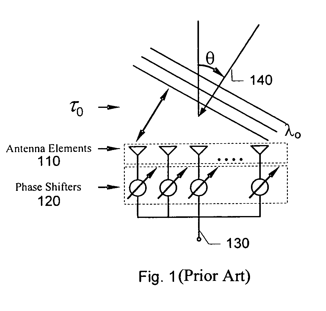
[0041]As shown in FIG. 1, the bandwidth of a phased array antenna can be limited by the bandwidth of the antenna elements 110 and the use of the phase shifters 120 for beam forming. For example, the antenna elements 110 form a linear array with N elements and element spacing dx. The beam former uses the following set of complex weights {1,exp⁡(j⁢⁢2⁢πλo⁢⁢1⁢dx⁢sin⁢⁢θo),exp⁢(j⁢⁢2⁢πλo⁢⁢2⁢dx⁢sin⁢⁢θo),…⁢⁢exp⁢(j⁢⁢2⁢πλo⁢⁢(N-1)⁢dx⁢sin⁢⁢θo)}

to form a beam in the direction of θo, and provides the optimal signal to noise gain for a signal at the center frequency fo. λo denotes the wavelength corresponding to fo. The output of t...


PUM


Abstract

System and method for signal processing and beam forming. A system for processing signals includes a first phase shifter, a second phase shifter, a first variable time delay system, and a second variable time delay system. Additionally, the system includes a first signal processing system and a sampling system. Moreover, the system includes a switching system and a measuring system.

Description

CROSS-REFERENCES TO RELATED APPLICATIONS[0001]The application claims priority to U.S. Provisional Application No. 60 / 426,453 filed Nov. 15, 2002, which is incorporated by reference herein.BACKGROUND OF THE INVENTION[0002]The present invention relates in general to detecting objects and / or areas. More particularly, the invention provides a method and system for adaptive variable true time delay beam forming. Merely by way of example, the invention is described as it applies to a phased array antenna, but it should be recognized that the invention has a broader range of applicability.[0003]A phased array antenna has been widely used for communications and radar systems. The phased array antenna usually does not mechanically steer antenna directions, and can provide rapid beam scanning. The directivity of the phased array antenna can be achieved by properly adjusting the relative phases between signals transmitted or received by different antenna elements. These antenna elements can re...

Claims


Application Information

Patent Timeline
Patent Type & Authority Patents(United States)
IPC IPC(8): H01Q3/26
CPCH01Q3/36H01Q3/2682
Inventor LAM, LAWRENCE K.RAMSEY, BOBBY L.
Owner LOCKHEED MARTIN CORP
Why Eureka
Try Eureka