
Multi-mode display

Inactive Publication Date: 2006-03-07
RPX CORP +1
View PDF19 Cites 34 Cited by
  • Summary
  • Abstract
  • Description
  • Claims
  • Application Information

AI Technical Summary

Benefits of technology

[0012]An advantage of the present invention is that it complies with existing industry standards while indicating to attached processors a mutually supportable display data signal format without excessive user interaction and undue delay.
[0013]Further advantages of the present invention include the ability to use off-the-shelf components having low power consumption requirements, and the ability to operate even when the display or display adapter is not powered on.

Problems solved by technology

Unfortunately, these existing standards do not enable a multi-mode display to indicate its entire set of supported image data signal formats.
Accordingly, a disadvantage of these existing standards involves situations where a particular processor supports some, but not all of the image data signal formats that a multi-mode display can support.
For example, if a display indicates to a processor a signal format that the processor does not support, the processor will be unable to send image data signals to the display, even though the processor may support other signal formats that are within the attached display's capabilities.
If a display does not comply with such standards, then it will not necessarily inter-operate with processors and graphics subsystems that are prevalent in the marketplace.

Method used


Image

  • Multi-mode display
  • Multi-mode display
  • Multi-mode display

Examples


Embodiment Construction

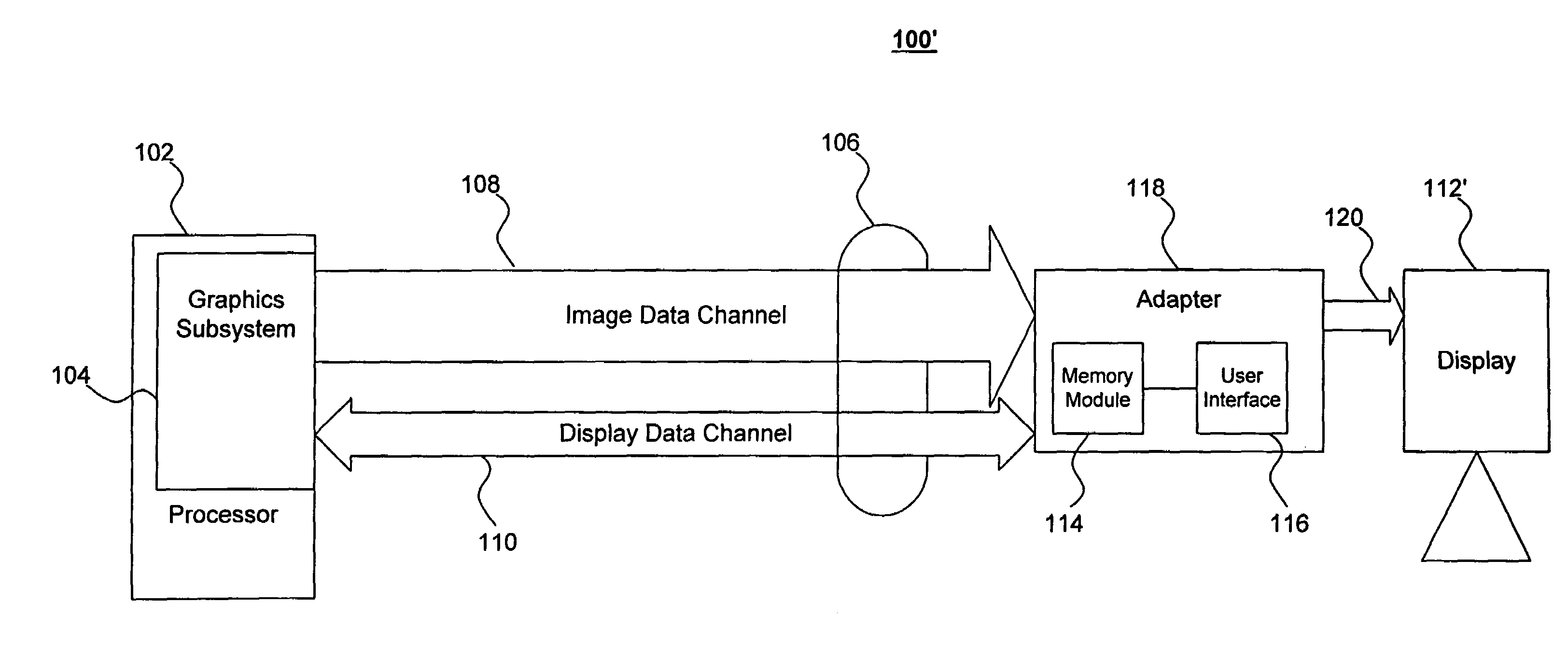
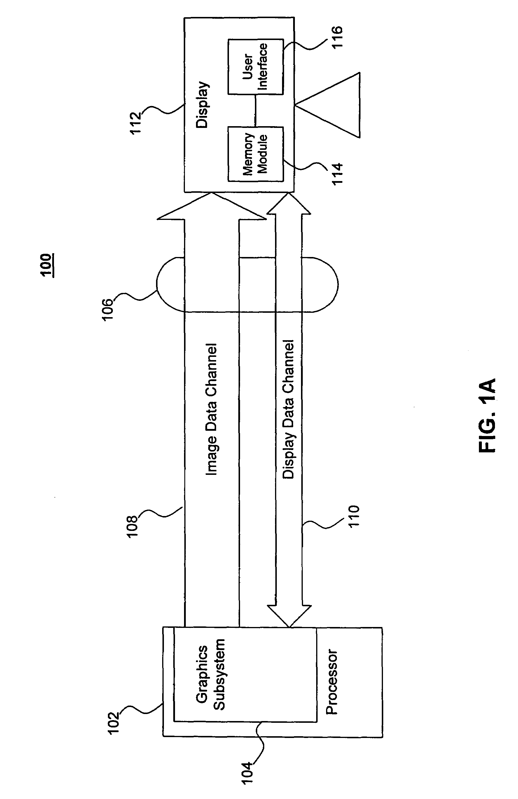
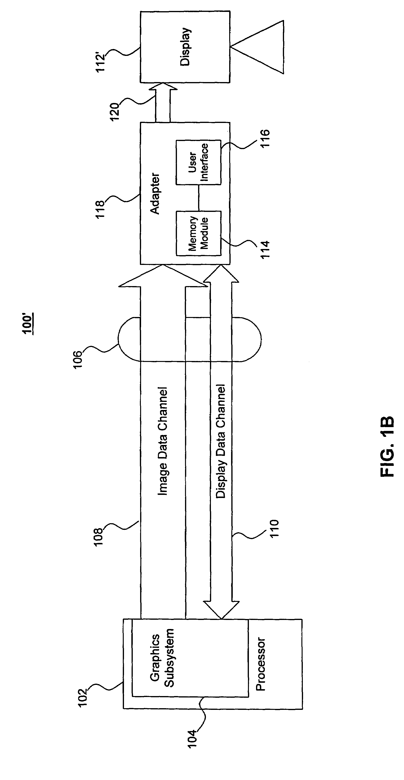
[0022]FIG. 1A illustrates an exemplary computer system 100 according to an embodiment of the present invention. Computer system 100 comprises a processor 102, a display interface 106, and a display 112. Processor 102 and display 112 are connected by display interface 106.

[0023]According to the present invention, processor 102 is a computing platform, such as a personal computer or a workstation. However, processor 102 can also be hardware, firmware, or any processing system capable of interacting with a graphical display, as would be apparent to a person skilled in the relevant art(s). In one embodiment, processor 102 includes a graphics subsystem 104. Graphics subsystem 104 receives commands from processing units (not shown) within processor 102. Based on these commands, graphics subsystem 104 sends image data signals to display 112. Display 112 receives these image data signals and converts them into images that are displayed to a user. Graphics subsystem 104 also engages in bi-di...


PUM


Abstract

A display is capable of displaying images in response to differently formatted signals. The display includes a switch that enables a user to select among a plurality of signal formats. The switch has a first setting that corresponds to a first of the plurality of signal formats and a second setting that corresponds to a second of the plurality of signal formats. The display also includes a memory module that receives requests from a channel and transmits a response associated with the setting of said switch.

Description

CROSS-REFERENCE TO RELATED APPLICATIONS[0001]This application is a continuation of U.S. patent application Ser. No. 09 / 575,457, entitled “MULTI-MODE DISPLAY,” filed May 22, 2000, now abandoned.BACKGROUND OF THE INVENTION[0002]1. Field of the Invention[0003]The present invention relates generally to the operation of graphical displays, and more particularly to the interface between a graphical display and a processor.[0004]2. Related Art[0005]Processing systems typically include a processor connected to a display through a display interface. Often, such processors contain graphics subsystems that directly handle the transfer of information, such as image data and control signals, between the processor and the connected display via the display interface. Multi-mode displays are capable of receiving image data signals in different formats, and displaying images in response to these differently-formatted signals. Image data signals are often categorized as being either digital or analog...

Claims


Application Information

Patent Timeline
IPC IPC(8): G06F13/14G06T1/60G09G5/00
CPCG09G5/006G09G2370/047G09G2360/02G09G2320/06
Inventor MENDELSON, JONATHAN D.MEDINA, OSCAR I.PONIATOWSKI, SUSAN R.
Owner RPX CORP
Learn More